
Laser identification installation positioning rule

A technology of laser marking and positioning ruler, which is applied in the direction of active optical measuring devices, measuring devices, instruments, etc., and can solve the problems of easy installation offset, installation of multi-line metal characters or attached signs, and heavy weight

Pending Publication Date: 2021-07-06
深圳市友昆标识制造有限公司
View PDF0 Cites 0 Cited by
  • Summary
  • Abstract
  • Description
  • Claims
  • Application Information

AI Technical Summary

Problems solved by technology

[0002] The sign industry is different from the construction and home improvement industries. It is impossible to accurately install complex multi-line metal characters or attached signs on the wall only with a laser level
At present, in the industry, workers usually use the waste boards left by the laser cutting and manufacturing of text marks as a "template", and install the text on the corresponding wall according to the template, but the problem is that this method cannot accurately locate the wall spacing and word margin of each text Moreover, the left waste board is bulky and heavy, and cannot be accurately fixed on the wall, resulting in labor-intensive and time-consuming installation, and it is easy to install offset. Moreover, when installing multi-line metal characters or attached signs in this way, it often fails to achieve the desired effect. Due to the installation accuracy, it cannot meet the requirements of the distance from the wall, the word spacing and the line spacing in the design, and because the strokes of the Chinese characters are trivial, it often causes problems that the strokes are not installed properly and the fonts are not beautiful.

Method used


Image

  • Laser identification installation positioning rule
  • Laser identification installation positioning rule
  • Laser identification installation positioning rule

Examples


Embodiment Construction

[0027] Example embodiments will now be described more fully with reference to the accompanying drawings. Example embodiments may, however, be embodied in many forms and should not be construed as limited to the examples set forth herein; Fully conveyed to those skilled in the art. The drawings are merely schematic illustrations of the present disclosure and are not necessarily drawn to scale. The same reference numerals in the drawings denote the same or similar parts, and thus repeated descriptions thereof will be omitted.

[0028] Furthermore, the described features, structures, or characteristics may be combined in any suitable manner in one or more example embodiments. In the following description, numerous specific details are provided in order to give a thorough understanding of example embodiments of the present disclosure. However, those skilled in the art will appreciate that the technical solutions of the present disclosure may be practiced without one or more of ...


PUM


Abstract

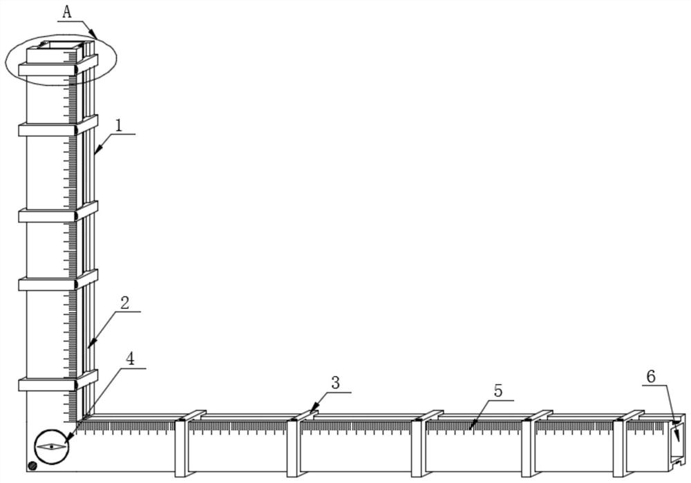
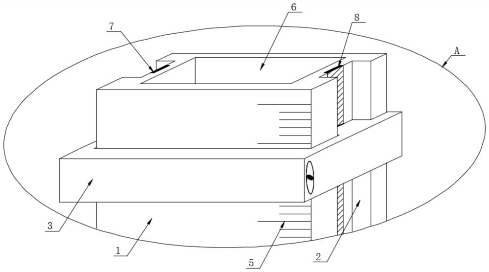
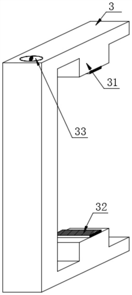
The invention discloses a laser identification installation positioning rule, and particularly relates to the technical field of identification industry application tools. The laser identification installation positioning rule comprises a positioning rule main body, the positioning rule main body comprises a vertical plate and a transverse plate which are vertically arranged, and the vertical plate and the transverse plate are of an integrated structure; scale marks are arranged on the edge of one side of the front face of the vertical plate and the edge of one side of the front face of the transverse plate, and a plurality of fixing assemblies are evenly distributed on the back face of the vertical plate and the back face of the transverse plate;the left and right sides of the vertical plate and the middle parts of the upper and lower sides of the transverse plate are provided with sliding rails; and a negative electrode metal sheet and a positive electrode metal sheet are fixedly embedded in the middle parts of the surfaces of the inner cavities of the two sliding rails on the vertical plate and the transverse plate respectively. A worker can conveniently select according to the actual installation environment of multiple rows of metal characters or attached identifiers, the application range is wide, and meanwhile, the laser beams emitted by the plurality of laser emitters on the sliding frame are staggered to form a grid, so that the distance to the wall edge, the character spacing and the row spacing can be accurately controlled in the design.

Description

technical field [0001] The invention relates to the technical field of marking industry application tools, and more specifically, the invention relates to a positioning ruler for laser marking installation. Background technique [0002] The sign industry is different from the construction and home improvement industries. It is impossible to accurately install complex multi-line metal characters or attached signs on the wall only with a laser level. At present, in the industry, workers usually use the waste boards left by the laser cutting and manufacturing of text marks as a "template", and install the text on the corresponding wall according to the template, but the problem is that this method cannot accurately locate the wall spacing and word margin of each text Moreover, the left waste board is bulky and heavy, and cannot be accurately fixed on the wall, resulting in labor-intensive and time-consuming installation, and it is easy to install offset. Moreover, when installi...

Claims


Application Information

Patent Timeline
IPC IPC(8): G01C15/00
CPCG01C15/004
Inventor 钟诚孔卫华欧文辉郎尚飞周志敏
Owner 深圳市友昆标识制造有限公司
Learn More