
Centering device and centering method of insulating pull rod in three-position switch

A technology of three-position switch and insulating pull rod, which is applied in the direction of electric switches, electrical components, circuits, etc., and can solve problems such as breakdown, uneven force on insulating pull rods, and poor mechanical strength

Pending Publication Date: 2021-07-06
CHINT ELECTRIC
View PDF6 Cites 0 Cited by
  • Summary
  • Abstract
  • Description
  • Claims
  • Application Information

AI Technical Summary

Problems solved by technology

[0002] The insulating rod is a key component in the GIS three-position switch. It has good dielectric strength, but its mechanical strength is slightly poor. The assembly quality of the insulating rod directly affects the stability and reliability of GIS operation.
However, due to the lack of a dedicated centering device, visual observation is usually used when assembling the insulating tie rods. This alignment method has poor accuracy and large errors, which makes the insulating tie rods unevenly stressed, and there is a risk of breaking after repeated operations. , In addition, if the insulating rod is eccentric, it will affect the accuracy of the opening and closing of the contact mechanism, resulting in failure to open and close normally or the risk of insulation breakdown, posing a safety hazard

Method used


Image

  • Centering device and centering method of insulating pull rod in three-position switch
  • Centering device and centering method of insulating pull rod in three-position switch
  • Centering device and centering method of insulating pull rod in three-position switch

Examples


Embodiment Construction

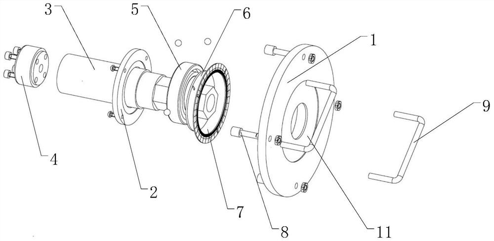
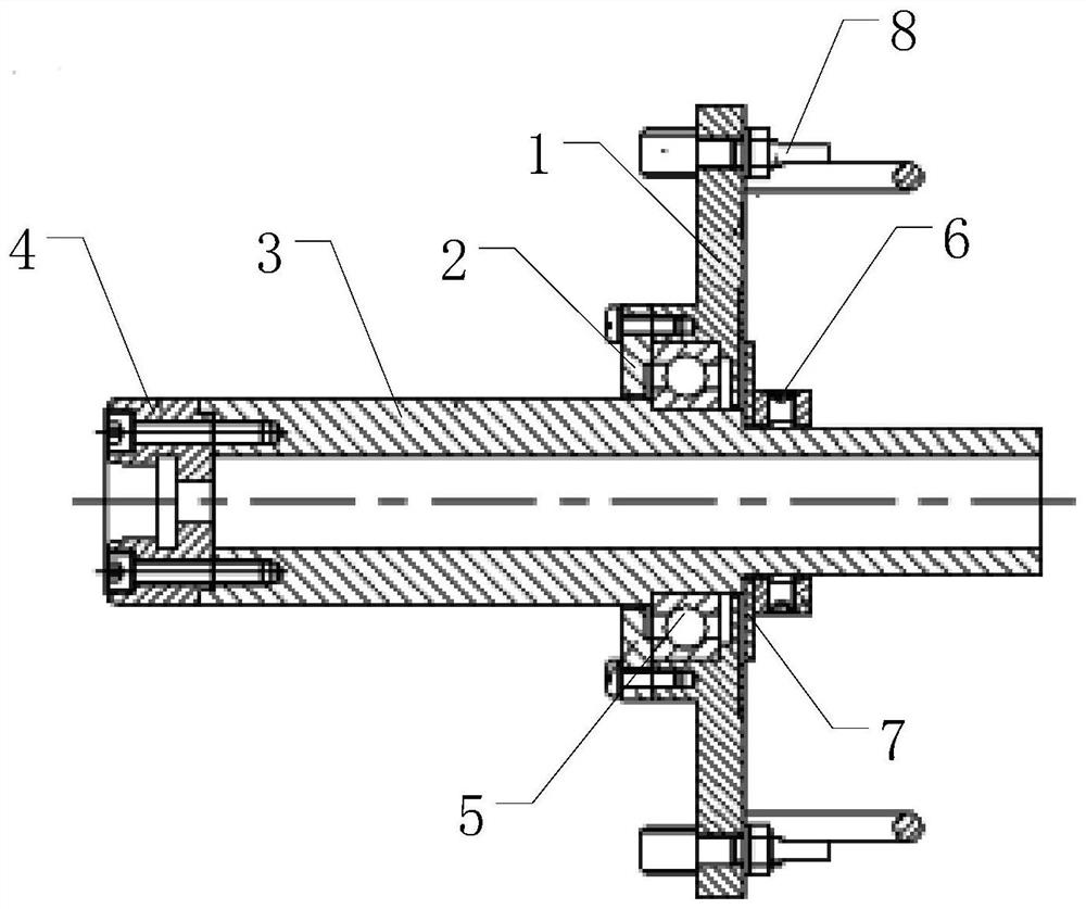
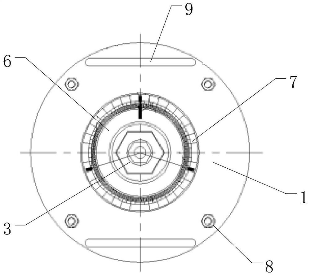
[0035] The following is attached Figures 1 to 12 The given examples further illustrate the specific implementation of a centering device and centering method for an insulating pull rod in a three-position switch of the present invention. A centering device and a centering method for an insulating pull rod in a three-position switch of the present invention are not limited to the description of the following embodiments.

[0036]A centering device for an insulating pull rod in a three-position switch, comprising a fixing structure, an adjusting structure, and an indicating structure linked with the adjusting structure, the fixing structure is used to be fixed on one side of the housing of the three-position switch a, the adjusting The structure is rotatably assembled on the fixed structure, and the adjusting structure is used to extend into the shell of the three-position switch a to drive the gear transmission shaft a1 of the three-position switch a to perform circular rotati...


PUM


Abstract

The invention relates to a centering device and a centering method of an insulating pull rod in a three-position switch, the centering device comprises a fixing structure, an adjusting structure and an indicating structure linked with the adjusting structure, the fixing structure is used for being fixed on one side of a shell of the three-position switch, the adjusting structure is rotatably assembled on the fixing structure, the adjusting structure is used for extending into a shell of the three-position switch to drive a gear transmission shaft of the three-position switch to perform circumferential rotation, and under the cooperation of the adjusting structure and the indicating structure, the relative position of the gear transmission shaft of the three-position switch and the contact mechanism is adjusted, and the insulating pull rod which is matched with the gear transmission shaft and the contact mechanism simultaneously meets the centering requirement during assembly. When the three-position switch is assembled, the relative positions of the gear transmission shaft and the contact mechanism are adjusted through the matching of the adjusting structure and the indicating structure, so that the insulation pull rod meets the centering requirement in the assembling process, high accuracy is achieved, and the situation that the three-position switch cannot be normally switched on and switched off due to the fact that the assembling error is too large and the assembling is not in place is avoided.

Description

technical field [0001] The invention relates to the field of high-voltage electrical appliances, in particular to a centering device and a centering method for an insulating pull rod in a three-position switch. Background technique [0002] The insulating rod is a key component in the GIS three-position switch. It has good dielectric strength, but its mechanical strength is slightly poor. The assembly quality of the insulating rod directly affects the stability and reliability of the GIS operation. However, due to the lack of a dedicated centering device, visual observation is usually used when assembling the insulating tie rods. This alignment method has poor accuracy and large errors, which makes the insulating tie rods unevenly stressed, and there is a risk of breaking after repeated operations. , In addition, if the insulating rod is eccentric, it will affect the accuracy of the opening and closing of the contact mechanism, resulting in failure to open and close normally...

Claims


Application Information

Patent Timeline
Patent Type & Authority Applications(China)
IPC IPC(8): H01H11/00
CPCH01H11/00
Inventor 高宁夏水银付春磊
Owner CHINT ELECTRIC
Learn More