Isolation switch triggering mechanism

A technology of triggering mechanism and isolating switch, applied in the direction of air switch parts, etc., can solve the problems of poor operation feeling and inconsistent force, etc.

Active Publication Date: 2021-07-06
安徽新高电气有限公司
View PDF4 Cites 1 Cited by
  • Summary
  • Abstract
  • Description
  • Claims
  • Application Information

AI Technical Summary

Problems solved by technology

[0004] The above-mentioned prior application still has deficiencies. The operating shaft is driven by the cam to move the locking plate, and the supporting spring is stretched or compressed when the operating shaft is turned. When the supporting spring is stretched or compressed to the maximum deformation, it will Generate elastic force to drive the operating shaft to reset instantaneously, and the operating shaft is hit at the moment of reset, and the operating shaft is hit at the moment of reset, so the force required for the entire operation process of the operating shaft is inconsistent, resulting in extremely poor operating experience

Method used


Image

  • Isolation switch triggering mechanism
  • Isolation switch triggering mechanism
  • Isolation switch triggering mechanism

Examples


Embodiment Construction

[0039] In order to enable those skilled in the art to better understand the technical solutions of the present invention, the present invention will be further described in detail below in conjunction with the accompanying drawings.

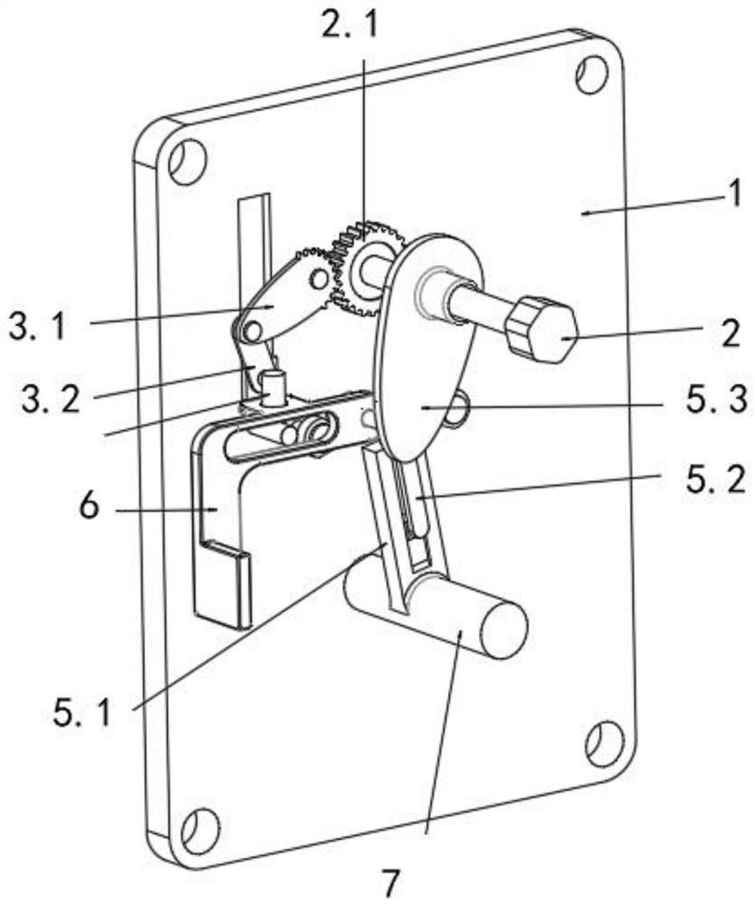
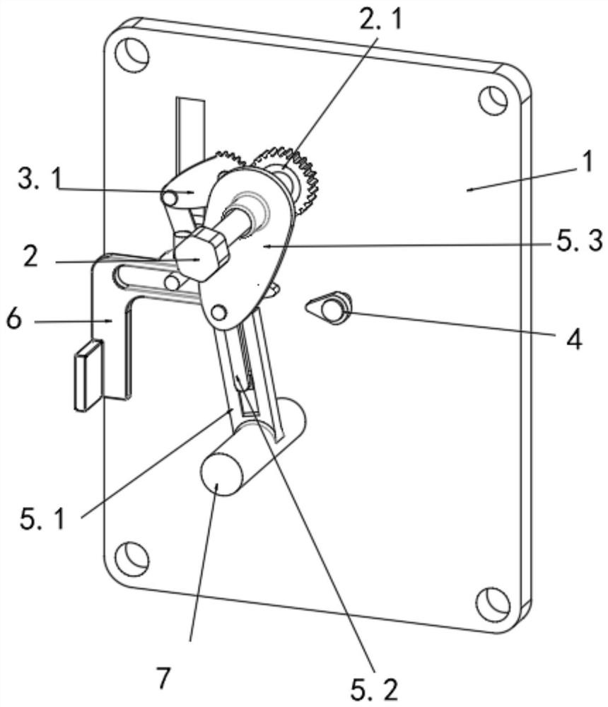
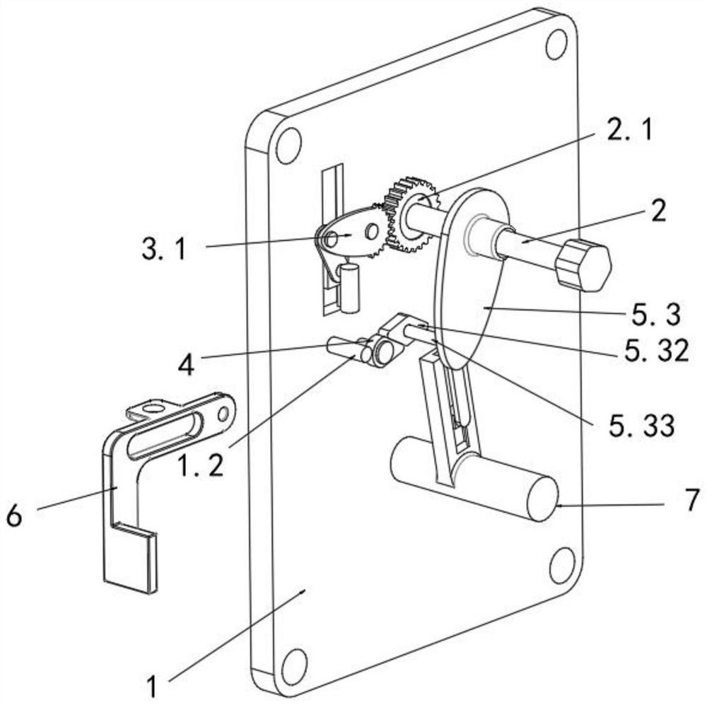
[0040] refer to Figure 1-12 As shown, a disconnect switch trigger mechanism includes a bottom plate 1, on which a rotating shaft 7 and an operating shaft 2 for opening and closing the isolating switch are arranged, a trigger mechanism is connected between the rotating shaft 7 and the operating shaft 2, and the trigger mechanism has Corresponding to the first position in the disconnected state of the operating shaft 2 and the second position in the closed state; also includes:

[0041] Two force application components, which are respectively placed on opposite sides of the bottom plate 1, and the force application components include connected elastic return parts and force application parts;

[0042] The trigger mechanism enters and leaves the f...


PUM


Abstract

The invention discloses an isolation switch triggering mechanism, and relates to the field of isolation switches. The isolation switch triggering mechanism comprises: a bottom plate, wherein a rotating shaft and an operating shaft for opening and closing an isolation switch are arranged on the bottom plate, and a triggering mechanism is connected between the rotating shaft and the operating shaft, and is provided with a first position corresponding to the open state of the operating shaft and a second position corresponding to the closed state of the operating shaft; and two force application assemblies arranged on the two opposite sides of the bottom plate respectively, wherein each force application assembly comprises an elastic reset piece and a force application piece which are connected, the triggering mechanism enters and breaks away from the first position to extrude one force application assembly, and the triggering mechanism enters and breaks away from the second position to extrude the other force application assembly. When the operating shaft is opened or closed, the force application assembly supports the triggering mechanism, the operating shaft is in a closed or opened state, and it is guaranteed that the acting force needed in the whole operation process of rotating the operating shaft is the same.

Description

technical field [0001] The invention relates to isolating switch technology, in particular to a triggering mechanism of an isolating switch. Background technique [0002] The isolating switch has an obvious disconnection point, which can realize the isolation function, and is mainly used for equipment maintenance. However, the isolating switch does not have a breaking function, and it cannot be opened and closed with a load. The obvious disconnection point cannot intuitively judge whether the circuit is disconnected, so it is not suitable for equipment maintenance. [0003] For example, the applicant’s previous application: the patent number is 201920125235.1, the date of authorization announcement is January 25, 2019, and the utility model patent named "A Circuit Breaker and Isolation Anti-Misoperation Interlocking Structure", which includes the base plate and the operating shaft , the outer wall of the operating shaft is clamped with an execution cam, the left part of th...

Claims


Application Information

Patent Timeline
Patent Type & Authority Applications(China)
IPC IPC(8): H01H31/02
CPCH01H31/02
Inventor 胡宏扬胡小龙张峰祁昊郑丁荣
Owner 安徽新高电气有限公司
Why Eureka
Try Eureka