Manufacturing device and method of vibration measuring tube

A vibration measurement and manufacturing device technology, applied in the field of mold manufacturing, can solve the problems of low manufacturing precision of vibration measuring tubes, and achieve the effects of fast processing speed, guaranteed precision and guaranteed precision.

Active Publication Date: 2020-07-10
ZHEJIANG SUPCON INSTR
View PDF6 Cites 1 Cited by
  • Summary
  • Abstract
  • Description
  • Claims
  • Application Information

AI Technical Summary

Problems solved by technology

[0004] The present invention aims to overcome the problem of low manufacturing precision of the vibration measuring tube in the prior art, and provide a manufacturing device and method for the vibration measuring tube that improves the manufacturing precision of the vibration measuring tube

Method used


Image

  • Manufacturing device and method of vibration measuring tube
  • Manufacturing device and method of vibration measuring tube
  • Manufacturing device and method of vibration measuring tube

Examples


Embodiment

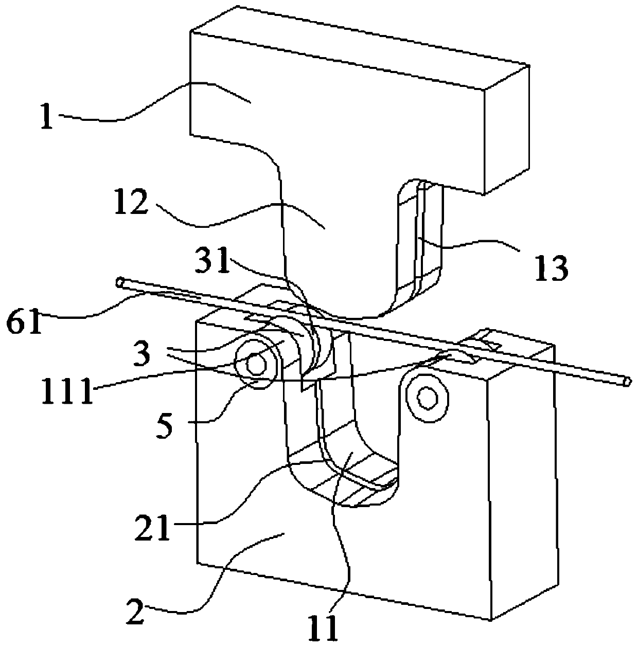
[0023] Embodiment: a kind of manufacturing device of vibrating measuring tube, as figure 1 As shown, it includes an upper mold 1 and a lower mold 2. The middle part of the lower mold has a depression 21 that the lower part of the upper mold can be inserted into. In the plane, the lower mold is provided with a lower mold pressure groove 22 corresponding to the upper mold, the centerlines of the upper mold pressure groove and the lower mold pressure groove are on the same plane, and the two sides of the lower mold depression are respectively provided with a gap between the measuring tube and the lower mold to reduce vibration. The friction roller mold 3, the axis of the roller mold is perpendicular to the center line of the lower mold pressure groove, the roller mold and the lower mold are connected by precision bearings 5, the two ends of the roller mold are respectively fixedly sleeved with the precision bearing inner ring, and the two precision bearing outer rings It is fixed...


PUM


Abstract

The invention discloses a manufacturing device of a vibration measuring tube. The manufacturing device comprises an upper mold and a lower mold. The middle portion of the lower mold is provided with asunken part capable of allowing the lower portion of the upper mold to be inserted in, and the lower portion of the upper mold is provided with a protrusion capable of being inserted into the sunkenpart. The lower portion of the upper mold is provided with an upper mold pressing groove used for cold-pressing the vibration measuring tube. The lower mold is provided with a lower mold pressing groove corresponding to the upper mold. The two sides of the sunken part of the lower mold are provided with roller molds capable of reducing friction force between the vibration measuring tube and the lower mold. The axes of the roller molds are perpendicular to the center line of the lower mold pressing groove. Each roller mold is provided with a circle of roller pressing groove. The invention further provides a manufacturing method of the vibration measuring tube. The manufacturing method comprises the steps of S1, feeding a vibration measuring tube blank into the lower mold pressing groove inthe upper surface of the lower mold, and driving the upper mold to move downwards to start to conduct cold-pressing; and S2, eliminating deformation generated in the cold-pressing process through a water expansion process. Through the manufacturing device and method of the vibration measuring tube, provided by the invention, the manufacturing precision of the vibration measuring tube can be improved.

Description

technical field [0001] The invention relates to the technical field of mold manufacturing, in particular to a manufacturing device and method for a vibration measuring tube. Background technique [0002] At present, the vibrating tube of the Coriolis mass flowmeter is one of its important parts. There are two main processing requirements: one is high precision itself, and the other is the consistency of the two vibrating tubes, so its processing is extremely difficult. Existing Coriolis mass flowmeter manufacturers generally use automatic pipe bending machines to process vibrating tubes. The automatic pipe bending machine realizes pipe bending through the rotation control of two axes and the feed control of one axis, in which the feed axis and the bending axis perform linear interpolation to complete the bending function, and the displacement of the two axes is determined by the bending The angle of the vibrating tube is determined, and the rotation axis is rotated and posi...

Claims


Application Information

Patent Timeline
Patent Type & Authority Applications(China)
IPC IPC(8): B21D35/00B21D7/06B21D26/033B21D26/047
CPCB21D35/002B21D7/06B21D26/033B21D26/047
Inventor 徐江均赵克安俞利明黄萍王志刚
Owner ZHEJIANG SUPCON INSTR
Why Eureka
Try Eureka