Camera device and electronic equipment

A camera and circuit board technology, applied in the field of electronic equipment, can solve problems such as inability to generate drivers and defects in imaging quality

Active Publication Date: 2021-07-06
VIVO MOBILE COMM CO LTD
View PDF3 Cites 0 Cited by
  • Summary
  • Abstract
  • Description
  • Claims
  • Application Information

AI Technical Summary

Problems solved by technology

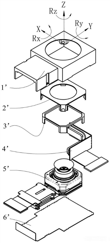
[0003] related technologies, such as figure 1 As shown, the bottom cover 6' corresponds to the setting of the lens assembly 5', and the micro-head uses a cross cardan shaft 2' to indirectly hang the lens assembly 5', and the cross cardan shaft 2' has four fulcrums, and two sets of two opposite corners The fulcrums are respectively connected to form the first rotating shaft and the second rotating shaft. The first rotating shaft and the second rotating shaft generally intersect vertically. The two supporting points corresponding to the first rotating shaft are respectively fixed on the first bracket 1'. The cross cardan shaft can be moved along the first Th

Method used


Image

  • Camera device and electronic equipment
  • Camera device and electronic equipment
  • Camera device and electronic equipment

Examples


Embodiment Construction

[0022] Embodiments of the present application will be described in detail below, examples of which are shown in the drawings, in which the same or similar reference numerals denote the same or similar elements or elements having the same or similar functions throughout. The embodiments described below by referring to the figures are exemplary, and are only for explaining the present application, and should not be construed as limiting the present application. Based on the embodiments in this application, all other embodiments obtained by persons of ordinary skill in the art without creative efforts fall within the protection scope of this application.

[0023] The features of the terms "first" and "second" in the description and claims of the present application may explicitly or implicitly include one or more of these features. In the description of the present application, unless otherwise specified, "plurality" means two or more. In addition, "and / or" in the specification ...


PUM


Abstract

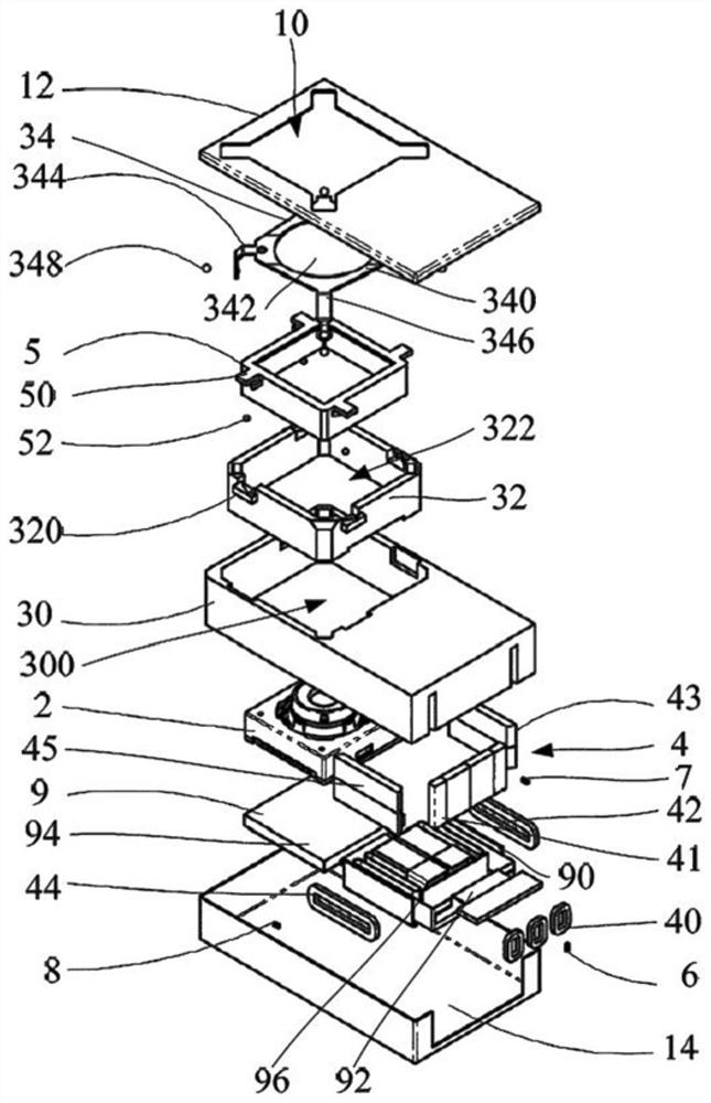
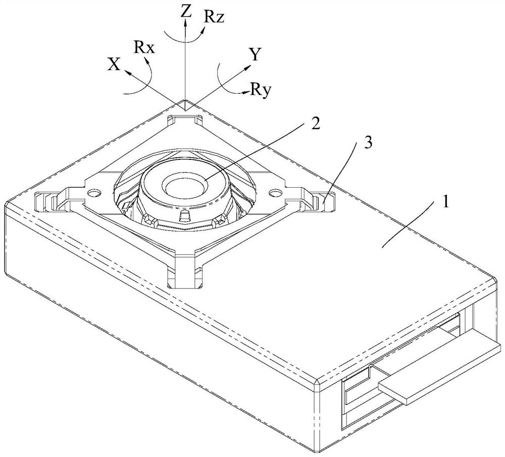
The invention discloses a camera device and electronic equipment. The camera device comprises a shell, a lens assembly, a bracket, a driving piece and a circuit board; an opening is formed in the shell, the support is arranged in the shell, and the lens assembly is rotationally connected with the support and is arranged opposite to the opening; the circuit board is arranged in the bracket and is connected with the lens assembly; the driving parts comprise the first driving part and the second driving part, the first driving part is arranged on the circuit board, the second driving part is arranged on the support, the second driving part and the first driving part are oppositely arranged, and the first driving part and the second driving part are used for driving the lens assembly to rotate around the optical axis of the lens assembly. According to the invention, the first driving part is arranged on the circuit board, the second driving part is arranged on the support, and the lens assembly rotates around the Z axis under the action of the first driving part and the second driving part, so jitter compensation in the Rz direction is realized, and the photographing quality is improved.

Description

technical field [0001] The present application belongs to the technical field of electronic equipment, and in particular relates to a camera device and electronic equipment. Background technique [0002] At present, with the continuous development of electronic equipment, people's requirements for taking pictures are getting higher and higher. The application of micro-cloud platform on mobile phones has greatly improved the picture quality when consumers take pictures with their hands. Generally, jitter can be decomposed into three directions of space X, Y, and Z, with a total of six degrees of freedom (movement along the X / Y / Z three-axis and rotation around the X / Y / Z three-axis: Rx, Ry , Rz). [0003] related technologies, such as figure 1 As shown, the bottom cover 6' corresponds to the setting of the lens assembly 5', and the micro-head uses a cross cardan shaft 2' to indirectly hang the lens assembly 5', and the cross cardan shaft 2' has four fulcrums, and two sets of ...

Claims


Application Information

Patent Timeline
IPC IPC(8): H04N5/225H04N5/232
CPCH04N23/50H04N23/55H04N23/51H04N23/685
Inventor 朱盼盼杨泽
Owner VIVO MOBILE COMM CO LTD
Why Eureka
Try Eureka