Flat antenna

An antenna, plane technology, applied in the direction of antenna, resonant antenna, electrical short antenna, etc., can solve the problems of isolation, dual polarization effect, reflector tendency and so on

Inactive Publication Date: 2003-12-10
INTEL CORP
View PDF2 Cites 1 Cited by
  • Summary
  • Abstract
  • Description
  • Claims
  • Application Information

AI Technical Summary

Problems solved by technology

[0004] In such an antenna configuration, comprising a column or row of radiating elements and a reflector arrangement at the trailing edge, there is a technical problem involving the reflector will

Method used


Image

  • Flat antenna
  • Flat antenna
  • Flat antenna

Examples


Embodiment Construction

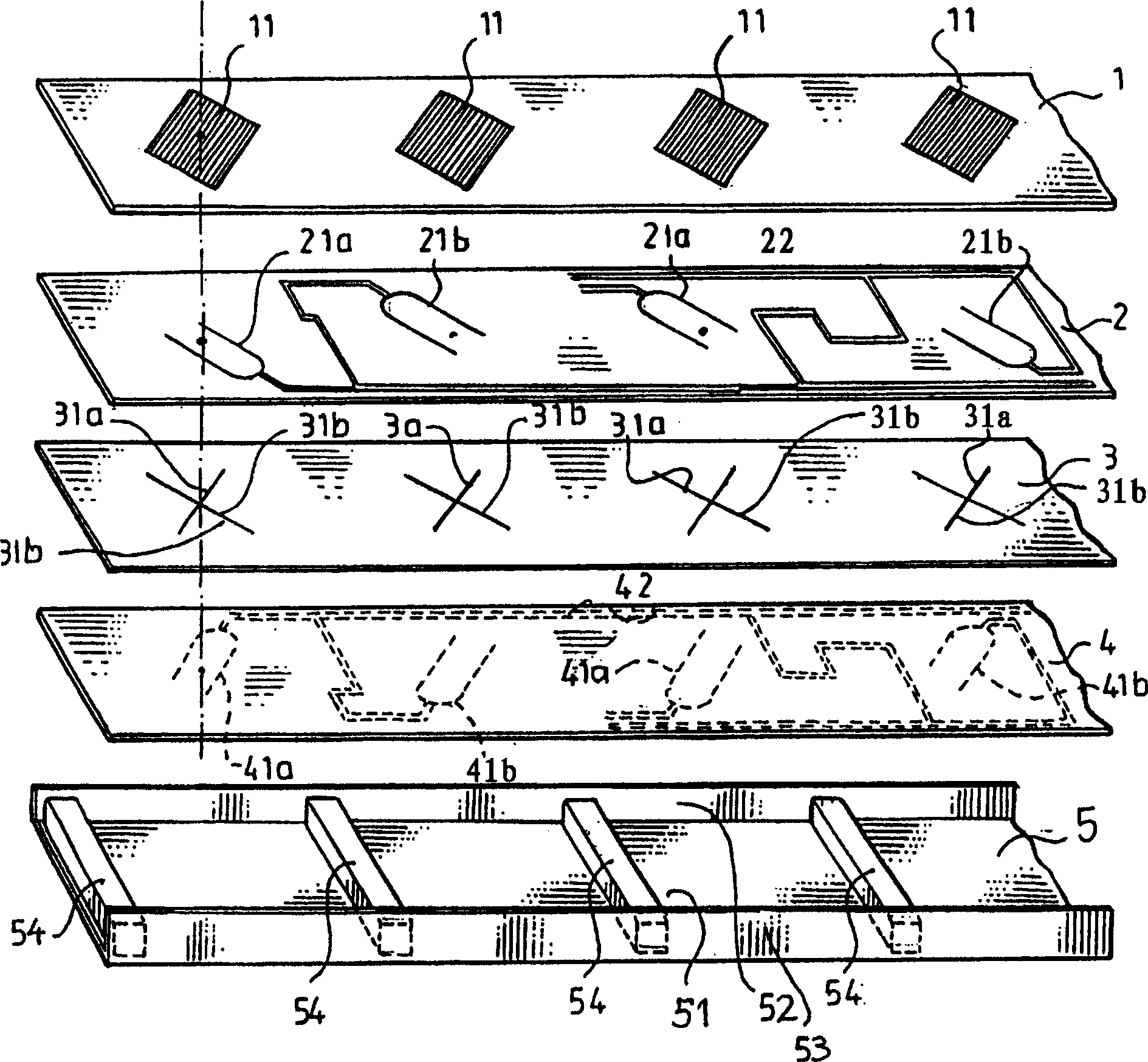
[0014] In the drawings, only the essential parts are shown which are important for the basic function of transmitting and receiving microwave energy contained in communication signals. Therefore, most necessary mechanical and electrical details have been omitted from the drawings.

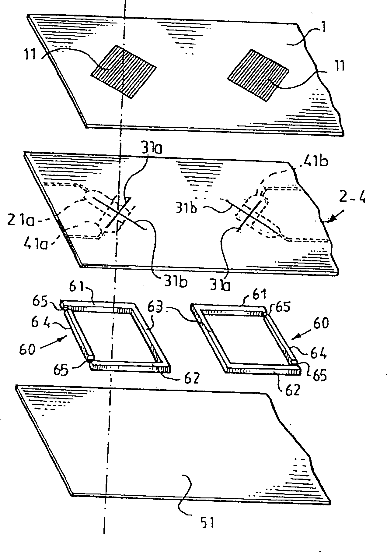
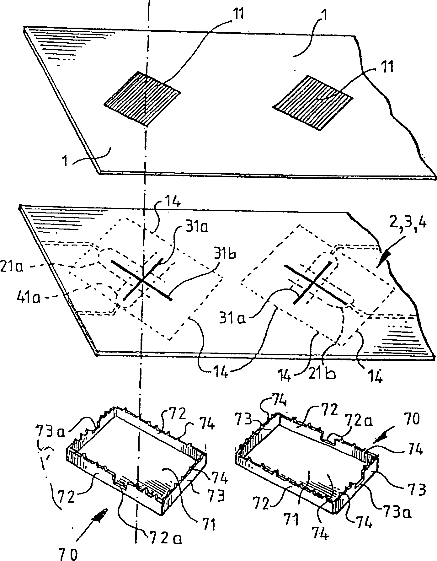
[0015] The antenna consists of a multi-layer structure, more specifically, the figure 1 In the first embodiment shown, there are 4 layers 1, 2, 3 and 4 arranged one above the other and placed on the bottom device 5 as a flat assembly, all layers 1-4 being substantially The top has the same dimensions in length and width and is fixed to the bottom unit 5 by mechanical means, for example in a longitudinal groove (not shown) of the bottom unit 5 or by special fasteners or snaps (not shown) And fixed.

[0016] The first layer 1 is made of a dielectric material and is provided with a number of emitting patches 11 arranged in longitudinal rows, preferably evenly spaced from each other. As everyone kno...


PUM


Abstract

A flat aperture-coupled antenna with a multilayer structure is disclosed. A rear side of the antenna comprises a metal reflector device including a hollow structure (3, 5) with separate box-like compartments, located in registry with radiating patches, corresponding pairs of orthogonal slots and feed elements, whereby microwave propagation within the hollow metal structure is substantially interrupted and any mutual coupling between the orthogonal slots is avoided.

Description

technical field [0001] The present invention relates to a substantially planar aperture-coupled antenna comprising a multilayer structure having a plurality of radiating plates arranged on a layer of dielectric material, a corresponding plurality of apertures, each in the form of two orthogonal slots, In a ground plane layer, and a plurality of corresponding feeding elements arranged in a feeding network on at least one flat plate, so that microwave energy is fed from said feeding element to said radiation sheet through two orthogonal slots so that the latter A microwave beam is formed propagating from the leading edge of the antenna, while the trailing edge includes a metal reflector arrangement. Background technique [0002] Similar planar hole coupled antennas are generally known in various embodiments, e.g. compare US Patent Specifications 5,030,961 (Tsao), 5,241,321 (Tsao), 5,355,143 (Zurcher et al.), and European Patent Application, No. 520908 (Alcatel Espace) . [0...

Claims


Application Information

Patent Timeline
IPC IPC(8): H01Q21/06H01Q9/04H01Q21/08
CPCH01Q21/08H01Q9/0457
Inventor 英厄拉·尼斯特伦比约恩·林德马克丹·卡尔松
Owner INTEL CORP
Why Eureka
Try Eureka