Device for recycling used batteries

A technology for recycling and processing batteries, applied in solid separation, classification, chemical instruments and methods, etc., can solve problems such as low efficiency, achieve high sorting efficiency, shorten overall processing time, and reduce time costs.

Pending Publication Date: 2021-07-09
安徽瑞露科技有限公司
0 Cites 0 Cited by

AI-Extracted Technical Summary

Problems solved by technology

[0003] The existing columnar decommissioned batteries need to be sorted before recycling. Different types of decommissioned batteries are processed in diffe...

Method used

In some optional embodiments, the front outer wall of the box body 1 is fixed with a downwardly inclined discharge pipe 11, and the upper end of the discharge pipe 11 is communicated with the discharge hole 10, so as to facilitate the discharge of decommissioned batteries .
[0031] Additionally, for simplicity of illustration and discussion, and so as not to obscure one or more embodiments of the present specification, integrated circuit (IC) chips and Known power/ground connections for other components. Furthermore, devices may be shown in block diagram form in order to avoid obscuring one or more embodiments of the description, and this also takes into account the fact that details ...

Abstract

The invention provides a device for recycling used batteries. The device comprises a box body; a feeding pipe is fixed to the top of the box body; supporting legs are fixed to the bottom of the box body; the box body is of a vertically-arranged round-cake-like structure; a rotating shaft is arranged in the box body in a rotationally connected manner; a motor is fixed to the back surface of the box body; the rotating shaft is sleeved with a fixing sleeve; a plurality of fixing plates are evenly distributed on the outer wall of the fixing sleeve along the center circumference of the rotating shaft; each fixing plate is provided with a recycling unit used for accommodating a used battery matched with the model of the recycling unit; the box body is further provided with a discharging unit; and the discharging unit is used for discharging the used batteries accommodated in the recycling units. Compared with a way of screening the used batteries with a screen, the recycling device provided by the invention has the advantages that different types of used batteries can be screened simultaneously, a high sorting efficiency is achieved, the overall processing time is shortened, the economic benefit of recycling is improved, and the time cost for recycling is lowered.

Application Domain

Grading

Technology Topic

Electric machineryProcess engineering +3

Image

  • Device for recycling used batteries
  • Device for recycling used batteries
  • Device for recycling used batteries

Examples

  • Experimental program(1)

Example Embodiment

[0017] In order to make the objects, technical solutions and advantages of the present disclosure, the present disclosure will be further described in detail below with reference to the specific embodiments.
[0018] It should be noted that the technical terms or scientific terms used in one or more embodiments of the present specification shall be understood by the disclosure of which is generally intended to have general skills in the art of the present disclosure. The "first", "second", and similar words used in one or more embodiments are not used in any order, quantity, or importance, but only different components. Similar words to "include" or "include", meaning that the elements or objects of the previously mentioned previously enumerated elements or objects that appear later in the word, without excluding other elements or objects. Similar words such as "Connect" or "Connect" are not limited to physical or mechanical connections, but may include electrical connections, whether direct or indirect. "On", "lower", "left", "right", etc., only to indicate the relative positional relationship, and the relative positional relationship may change accordingly when the absolute position of the object is described.
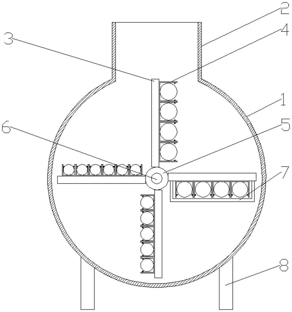
[0019] In this specification, one or more embodiments disclose a recovery processing apparatus for retiring a battery, including a case 1, and an add tube 2 is fixed at the top, and the bottom of the casing 1 fixes a leg 8, the The casing 1 is a roller structure that is vertically disposed, and the inner portion of the box 1 is provided with a rotating shaft 6 that is rotatably coupled to the central axis of the casing 1, and the back side of the box is fixed. There is a motor 9, and the output shaft of the motor 9 is fixedly coupled to the rotation shaft 6, and the rotating shaft 6 is provided with a fixed sleeve 5, and the outer wall of the fixed sleeve 5 has a plurality of fixed sleeve along the center of the rotation shaft 6. On the plate 3, the fixing plate 3 is provided with a recovery unit, and the recovery unit on each fixing plate 3 corresponds to a model of retired battery, which is used to accommodate a retired battery corresponding to its model, the box. A discharge unit is also provided on the body 1, which is used to discharge the retired battery accommodated by the recovery unit.
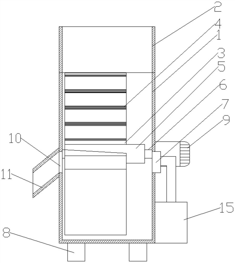
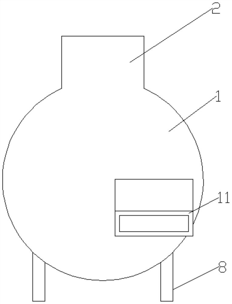
[0020] Such as Figure 1-4 As shown, the recovery processing apparatus includes a casing 1, and the bodies 1 is welded to the bodied foot 8, and the leg 8 is used to support the casing 1, the casing 1 is a vertical circular cake structure, and the inner is provided with rotation connection. The rotating shaft 6, the back surface of the casing 1 is fixed to the motor 9, the motor 9 output shaft is fixed to the rotation shaft 6, and the motor 9 is used to drive the rotation shaft 6 to rotate, the rotation shaft 6 is provided with a fixed sleeve 5, fixed sleeve 5 The outer wall is covered with a plurality of fixed plates 3, and a recovery unit is provided on the fixing plate 3, and the recovery unit on each fixing plate 3 is relative to a model of the battery, and the recovery unit is used to accommodate the retired battery corresponding to its model. A discharge unit is also provided on the casing 1, and the discharge unit is used to discharge the recovered battery.
[0021] The principle of use of the device is: from the addition pipe 2, the retired battery is continuously poured, drive the rotation shaft 6 by the motor 9, and the rotation shaft 6 drives the fixing sleeve 5 to rotate to rotate the fixing plate 3, each fixing plate 3 The recovery unit only reclaims its corresponding retired battery, and the respective recovery units are recovered by the continuous rotation of the fixing plate 3, and then discharge the recovered retired battery by the discharge unit by the discharge unit. Classification recycling work.
[0022] The recovery processing apparatus provided by the present invention, which is compared to the screen screening, and simultaneous screening can simultaneously screen different models, high selection efficiency, shorten the overall processing time, improve the economic benefits of recovery, and reduce the time cost of recovery.
[0023] In some optional embodiments, the front end of the fixing plate 3 is bonded to the inner wall of the front end of the casing 1, and a gap is left between the rear end of the fixing plate 3 and the rear end inner wall of the casing 1. The unit includes a plurality of recovery grooves 4, the recovery groove 4 fixed to one side of the fixing plate 3 facing its rotation direction, the cross section of the recovery tank 4 is a concave shape, the recovery tank 4 parallel to the rotation shaft 6 The length direction, the inner wall width of the recovery tank 4 is a diameter length of the retired battery having a corresponding model, and the inner wall of the recovery groove 4 is connected to the rotary plate 12, and the upper end of the rotary plate 12 is provided with fixed in recovery. A spring 13 is fixed to the inner wall of the groove 4, and a spring 13 is fixed to the inner wall of the recovery groove 4, the spring 13 for keeping the rotating plate 12 vertically vertically. The state of the rotating plate 12 is defined in the bottom of the recovery tank 4 in the state of the recovery tank 4 side wall.
[0024] Such as Figure 4 As shown, the turning plate 12 is held horizontally by the spring 13, and the rotating plate 12 can only be rotated at the bottom of the recovery groove 4, and cannot be rotated above the recovery groove 4, and the restricted plate 14 is disposed above the rotating plate 12, and the direction of rotation It is defined, so that the retired battery corresponding to the inner wall width of the recovery tank 4 can only be entered into the recovery groove 4 by the casing 1, and cannot be separated from the upper opening of the recovery groove 4, and the larger-scale retired battery cannot enter the recovery tank 4. Inside, while the retired battery in which the smaller type is inserted into the recovery tank 4, as the fixing plate 3 is rotated, when the recovery groove 4 is down, the smaller type retired battery is dropped, the fixed plate 3 and the box body 1 There is a gap between the inner walls of the back, for the dropped retired battery to return to the bottom of the casing 1 during the rotation, so as to be sorted again, with the continuous rotation of the fixing plate 3, the recovery groove 4 gradually collected and For the retired battery of the corresponding model, the simultaneous sorting of different types of retired batteries is achieved.
[0025] In some alternative embodiments, the rotation direction of the fixing plate 3 is rotated clockwise, and the outer wall of the box 1 is opened, and the bore 10 is a rectangular hole disposed horizontally. The material hole 10 is coincident with the radius of the upper right end in front of the casing 1, the discharge unit including air pump 15 and nozzle 7 fixed to the inner wall of the casing 1, and the spray head 7 is aligned with the discharge hole 10, said The output of the air pump 15 is connected to the nozzle 7 through the pipe.
[0026] Such as Figure 1-3 As shown, after the fixing plate 3 is rotated for a certain period of time, the number of batteries corresponding to the corresponding model in the recovery groove 4 gradually increases, and when the fixing plate 3 is rotated to the position of the discharge hole 10, the motor 9 is suspended, and then the air pump 15 is discharged. Air, and sprayed from the spray head 7, the battery in the recovery groove 4 cannot fall from its opening, but can slide out from both ends of the recovery groove 4, and the front end of the fixed plate 3 and the front end of the box 1 The inner wall bonded, the compressed air discharged from the spray head 7 causes the retired cell in the recovery groove 4 to the discharge hole 10 direction from the end portion of the recovery groove 4, and finally discharge from the discharge hole 10, place the recovery box in front of the box 1, The retired battery that falls from the discharge hole 10 can be collected.
[0027] In some alternative embodiments, the outer wall of the casing 1 fixes a downwardly inclined discharge tube 11, and the upper end of the tube 11 is in communication with the discharge hole 10 for the discharge of the retired battery.
[0028] In some optional embodiments, such as figure 2 As shown, the fixing plate 3 is backward in the direction of rotation, and the front end of the fixing plate 3 is a higher end, and when the recovery groove 4 is rotated to the opening downward position, its interior smaller type battery And the upper larger type battery starts to fall, and falls below the back surface of the fixed plate 3, the back surface of the fixing plate 3 is an inclined surface, which is convenient to re-roll down to the fastening plate 3 and the casing with the battery that does not correspond to the recovery tank 4. 1 Among the gaps in the inner wall of the back, and reap back to the bottom of the box to facilitate subsequent sorting.
[0029] The specific embodiment of the present specification is described above. Other embodiments are within the scope of the appended claims. In some cases, the operation or steps described in the claims may be performed in a sequence different from the embodiments and can still achieve desired results. In addition, the desired results can be achieved in a particular order or continuous order depicted in the drawings. In certain embodiments, multi-tasking and parallel processing can also be possible may or may be advantageous.
[0030] One of ordinary skill in the art will appreciate that the discussion of any of the above embodiments is merely illustrative, and is not intended to impose that the scope of the disclosure (including the claim) is limited to these examples; in the idea of ​​the present disclosure, the above embodiment or A combination can also be performed between the technical features in different embodiments, and the steps can be implemented in any order, and there are many other changes in different aspects of the present specification as described above, in order to concise them are not in detail. provide.
[0031] In addition, in order to simplify the description and discussion, and in order not to understand the present specification, it is difficult to understand, or may be shown or may not be shown or may not be shown in the accompanying circuit (IC) chip and other components. A well-known power / ground connection. Further, the apparatus can be shown in the form of a block diagram to avoid being difficult to understand the present specification, and this also considers the fact that the details of the implementation of these block diagram devices are high depending on the implementation of this The platform of one or more embodiments (ie, these details should be completely within the scope of the invention). In the case of the exemplary embodiments of the present disclosure, it will be apparent to those skilled in the art, it will be apparent to those skilled in the art, and may change without these specific details or these specific details. One or more embodiments of the present specification are implemented. Therefore, these descriptions should be considered as illustrative and not restrictive.
[0032] Although the present disclosure has been described in connection with the specific embodiments of the present disclosure, many replacements, modifications, and variations of these embodiments will be apparent to those of ordinary skill in the art. For example, other memory architecture (eg, dynamic RAM (DRAM)) can use the embodiments discussed.
[0033] One or more embodiments are intended to cover all such alternatives, modifications, and variants falling within the broad range of the appended claims. Therefore, any otherwise omitted, modified, equivalent replacement, improvement, etc. of the present specification, etc., should be included within the scope of the present disclosure.

PUM

no PUM

Description & Claims & Application Information

We can also present the details of the Description, Claims and Application information to help users get a comprehensive understanding of the technical details of the patent, such as background art, summary of invention, brief description of drawings, description of embodiments, and other original content. On the other hand, users can also determine the specific scope of protection of the technology through the list of claims; as well as understand the changes in the life cycle of the technology with the presentation of the patent timeline. Login to view more.

Similar technology patents

Logistics sorting device

ActiveCN111891681AImprove sorting efficiencyImprove logistics delivery efficiency
Owner:荣智工企智能技术(昆山)有限公司

Intelligent sorting machine used for electronic commerce

ActiveCN108509557ASave manual sorting timeImprove sorting efficiency
Owner:长汀县安邸家具有限公司

Steel bar lifting and picking device

Owner:TAIYUAN UNIVERSITY OF SCIENCE AND TECHNOLOGY

Classification and recommendation of technical efficacy words

  • Improve sorting efficiency
  • Reduce overall processing time

Intelligent warehouse system

Owner:哈尔滨灵翰智能技术有限公司

Extensible inspection production equipment for smart cards

InactiveCN101049595AImprove sorting efficiencygood sorting quality
Owner:GUANGZHOU SANTUO IDENTIFICATION TECH CO LTD

Coin classification arrangement system

Owner:CHONGQING JIAOTONG UNIVERSITY +1

Small and medium-sized city household garbage sorting treatment system and method

ActiveCN108580520AImprove sorting efficiencyAchieving precision and efficiency
Owner:BEIJING UNIVERSITY OF CIVIL ENGINEERING AND ARCHITECTURE

Laser surface processing equipment

InactiveCN110216369AReduced steps for laser surface treatmentReduce overall processing time
Owner:WUHAN HGLASER ENG CO LTD +1
Why Eureka
Try Eureka