Automatic coupling assembly line based on machine vision

A machine vision and coupling technology, applied in assembly machines, metal processing, metal processing equipment, etc., can solve the problems of poor safety and low efficiency, and achieve the effect of zero defective rate and high efficiency

Active Publication Date:
View PDF12 Cites 0 Cited by
  • Summary
  • Abstract
  • Description
  • Claims
  • Application Information

AI Technical Summary

Problems solved by technology

[0004] In view of this, the object of the present invention is to provide an automatic assembly line for couplings based on machine vision that realizes automatic and accurate assembly, so as to solve the technical problems of low efficiency and poor safety in the prior art

Method used


Image

  • Automatic coupling assembly line based on machine vision
  • Automatic coupling assembly line based on machine vision
  • Automatic coupling assembly line based on machine vision

Examples


Embodiment Construction

[0040] The preferred embodiments of the present invention will be described in detail below with reference to the accompanying drawings, but the present invention is not limited to these embodiments. The present invention covers any alternatives, modifications, equivalent methods and schemes made within the spirit and scope of the present invention.

[0041] In order to provide the public with a thorough understanding of the present invention, specific details are set forth in the following preferred embodiments of the present invention, but those skilled in the art can fully understand the present invention without the description of these details.

[0042] In the following paragraphs the invention is described more specifically by way of example with reference to the accompanying drawings. It should be noted that the accompanying drawings are all in a relatively simplified form and in an inaccurate scale, and are only used to facilitate and clearly assist in explaining the p...


PUM


Abstract

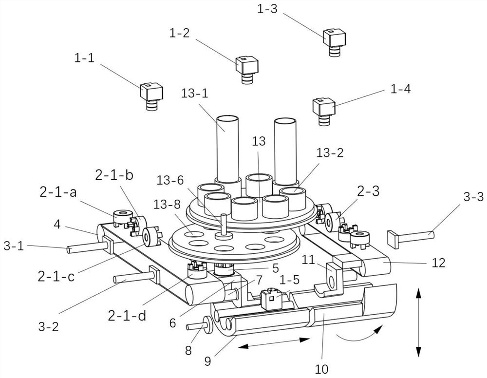
The invention discloses an automatic coupling assembly line based on machine vision. The assembly line comprises a left side platform, a right side platform, an elastomer assembling table, a left-right assembling platform and a camera group, the left side platform is used for conveying left half couplings, enabling the left half couplings with upward gaps to be normally conveyed to the lower part of the elastomer assembling table, and aligning and assembling with an elastomer to form a coupling suite, the right side platform is used for conveying the right half couplings in different directions so that gaps of the right half couplings located on a second assembling platform face the left side, the elastomer assembling table receives the elastomer and conveys the received elastomer into an assembling hole, the elastomer is pressed into the left half couplings with the upward gaps through an assembling pressing rod, the left-right assembling platform comprises a first assembling platform and the second assembling platform, the first assembling platform is used for receiving the coupling suite, the second assembling platform is used for receiving the right half couplings, and the camera group is used for identifying the positions and directions of the left half couplings, the elastomer and the right half couplings and conveying identification results to the left side platform, the right side platform and the left-right assembling platform.

Description

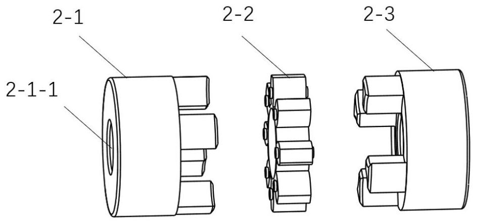
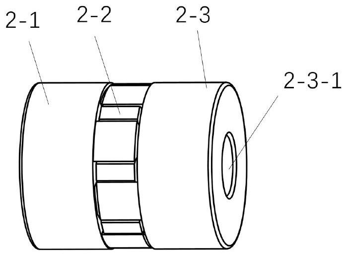
technical field [0001] The invention relates to the technical field of coupling assembly, in particular to an automatic assembly line for couplings based on machine vision. Background technique [0002] The plum blossom coupling is a kind of flexible coupling, which is used in various mechanical equipment and mechanical devices to realize the connection between shafts and transmit torque and power. my country's total demand for couplings in 2017 was 54.2 billion yuan, and plum blossom couplings accounted for a large share. With the rapid development of the national economy, the demand for plum blossom couplings is also increasing year by year. [0003] However, the plum blossom couplings of the prior art are all manually installed, such as figure 1 As shown, after manually aligning the left half-coupling 2-1, the plum-shaped elastic body 2-2, and the right half-coupling 2-3, start the pneumatic device (usually use a foot to step on the pneumatic switch), and the pneumatic ...

Claims


Application Information

Patent Timeline
Patent Type & Authority Applications(China)
IPC IPC(8): B23P21/00B23P19/10
CPCB23P21/004B23P19/102
Inventor 赵明岩李一欣林敏梁明轩胡剑虹陶伟鹏李运良
Why Eureka
Try Eureka