Multi-directional mechanical arm for 3D printing

A 3D printing and robotic arm technology, applied in manipulators, manufacturing tools, etc., can solve problems such as poor quality, nozzle larger than part error, nozzle vibration, etc., to achieve good suspension flexibility, prevent nozzle shaking, and increase accuracy.

Inactive Publication Date: 2021-07-09
南昌升升科技有限公司
View PDF0 Cites 2 Cited by
  • Summary
  • Abstract
  • Description
  • Claims
  • Application Information

AI Technical Summary

Problems solved by technology

[0003] At present, the mainstream 3D printers on the market are most widely used in the form of fused deposition manufacturing. However, this forming method cannot print some parts with suspended parts. The direction of movement of the nozzle of the printer is single, and the nozzle is only in one direction , the extruded material port is parallel to the workbench, and the nozzle cannot rotate in the air to change the spraying direction of the nozzle when it is moving. At the same time, the nozzle is not fixed enough when it rotates above the platform, so that the nozzle will vibrate when it moves, resulting in the nozzle Errors will occur when it is larger than the part, and the quality of the larger product is not acceptable

Method used


Image

  • Multi-directional mechanical arm for 3D printing
  • Multi-directional mechanical arm for 3D printing
  • Multi-directional mechanical arm for 3D printing

Examples


Embodiment Construction

[0023] Next, the technical solutions in the embodiments of the present invention will be apparent from the embodiment of the present invention, and it is clearly described, and it is understood that the described embodiments are merely embodiments of the present invention, not all of the embodiments. Based on the embodiments of the present invention, there are all other embodiments obtained without making creative labor without making creative labor premises.

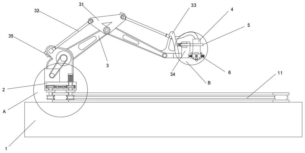
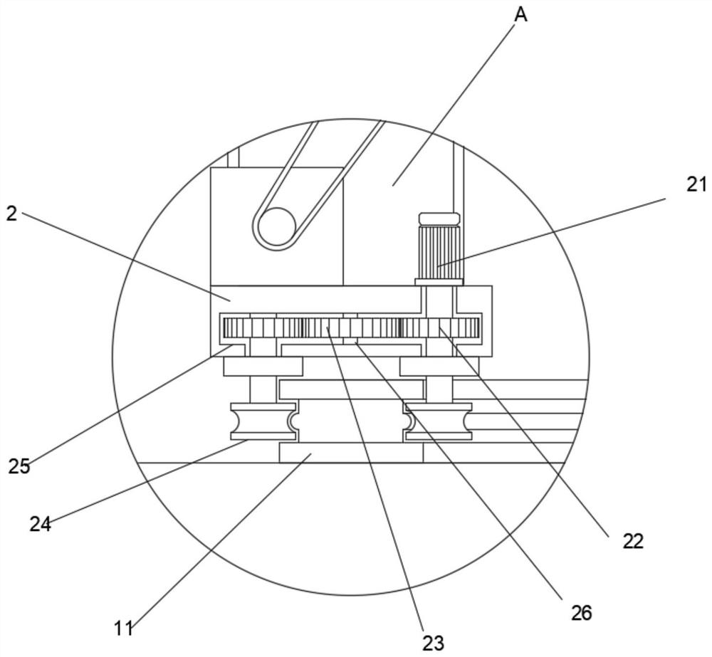
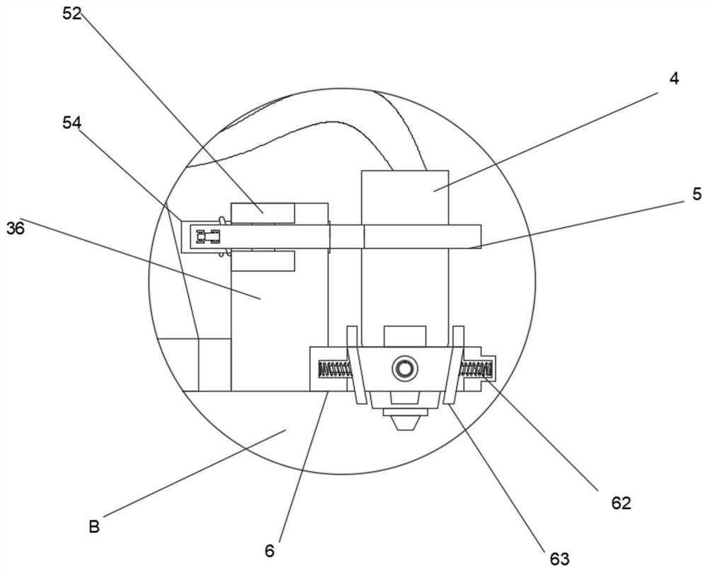
[0024] See Figure 1 to 6 The present invention provides a technical solution: one 3D printing multi-directional robot arm, including the base 1, the swing arm 3, the nozzle 4, and the casing 5, the upper surface of the base 1 is provided with curved rail 11, curved smooth The upper end of the left side of the rail 11 slides a moving seat 2, and the lower surface of the moving seat 2 is provided with two sets of roller 24, and the two sets of roller 24 are engaged on the left and right sides of the curved rail 11, and the up...


PUM


Abstract

The invention relates to the technical field of 3D printers, in particular to a multi-directional mechanical arm for 3D printing, The multi-directional mechanical arm comprises a base, two swing arms, a spray head and a clamping rod, an arc-shaped sliding rail is arranged on the upper surface of the base, a movable seat is slidably connected to the upper end of the left side of the arc-shaped sliding rail, a fixed seat is arranged at the rear end of the upper surface of the movable seat, and the two swing arms are hinged to the upper end of the fixed seat; a triangular plate is hinged to the outer side of a connection position of the two swing arms, telescopic rods are arranged on the left side and the right side of the triangular plate, a rotating plate is fixed to the other end of the telescopic rod on the right side, a fixed plate is fixed to the right side of the rotating plate, the clamping rod is arranged at the upper end of the fixed plate, the spray head is arranged on the inner side of the clamping rod, and a plurality of moving plates are arranged on the lower end of the spray head; and a fixing ring is arranged at the outer side end of each moving plate, and the left side ends of the fixing rings are fixed to the lower end of the fixed plate. The movable seat can rotate on the arc-shaped sliding rail, the telescopic rod drives the rotating plate at the right end to rotate, and when the mechanical arm rotates in multiple directions, the spray head is doubly protected through the clamping rod and the fixing rings.

Description

Technical field [0001] The present invention relates to the field of 3D printer, in particular a 3D printing multi-directional robotic arm. Background technique [0002] 3D printing technology The method of forming the raw material layer stacking the raw material layer is stacked by a computer and a 3D printer connection, with an adhesive such as a metal or plastic as a printing material, a graphic graphic printing out of the model by a digital model. Technical means, 3D printing techniques can be manufactured with a part of any complexity without complex machining or mold as compared to the conventional reduction method. [0003] At present, the mainstream 3D printer sold on the market is the most widely used in the formation of melt deposition, but this forming method cannot print some parts with suspended parts, the printer's nozzle movement direction is single, the nozzle is only one direction The port of the extruded material is parallel to the workbench, and the nozzle cann...

Claims


Application Information

Patent Timeline
Patent Type & Authority Applications(China)
IPC IPC(8): B25J11/00
CPCB25J11/0075
Inventor 不公告发明人
Owner 南昌升升科技有限公司
Why Eureka
Try Eureka