Plastic film blowing machine

A film blowing machine and plastic technology, which is applied in the field of plastic processing, can solve the problems of affecting the cooling effect, reducing the cooling efficiency, and reducing the cooling efficiency, and achieve the effects of shortening the solidification time, improving the cooling effect, and improving the cooling utilization rate.

Inactive Publication Date: 2021-07-09
唐集体
View PDF0 Cites 2 Cited by
  • Summary
  • Abstract
  • Description
  • Claims
  • Application Information

AI Technical Summary

Problems solved by technology

[0003] First of all, when the cooling air is blown out, it first passes through the bottom of the film bubble, then continues to flow upwards, and is finally sucked away from the exhaust pipe. When the cooling air passes through the position below the film bubble, because this position is closest to the extrusion port, making The temperature is the highest on the entire film bubble. When the cooling air flow passes through this position, the heat of the film bubble is taken away, and when it passes through other positions of the film bubble, the cooling effect is reduced, which in turn leads to a decrease in cooling efficiency.
[0004] Secondly, in the original setting of the blown film die head, due to the plastic stored inside the blown film die head, its temperature is relatively high, and the outlet channel of the cooling air flow is close to the blown film die head, so that the temperature of the cooling air flow is relatively high when it passes out , so that the cooling efficiency is reduced. At the same time, under the action of the exhaust pipe, the cooling airflow is always directly sucked into the exhaust pipe from the air inlet, so that the film bubble above the exhaust pipe cannot be cooled by the cooling airflow, which affects the cooling effect.

Method used


Image

  • Plastic film blowing machine
  • Plastic film blowing machine
  • Plastic film blowing machine

Examples


Embodiment Construction

[0018] The following will clearly and completely describe the technical solutions in the embodiments of the present invention with reference to the accompanying drawings in the embodiments of the present invention. Obviously, the described embodiments are only some, not all, embodiments of the present invention. Based on the embodiments of the present invention, all other embodiments obtained by persons of ordinary skill in the art without making creative efforts belong to the protection scope of the present invention.

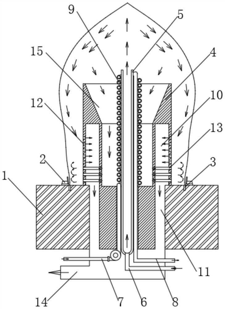
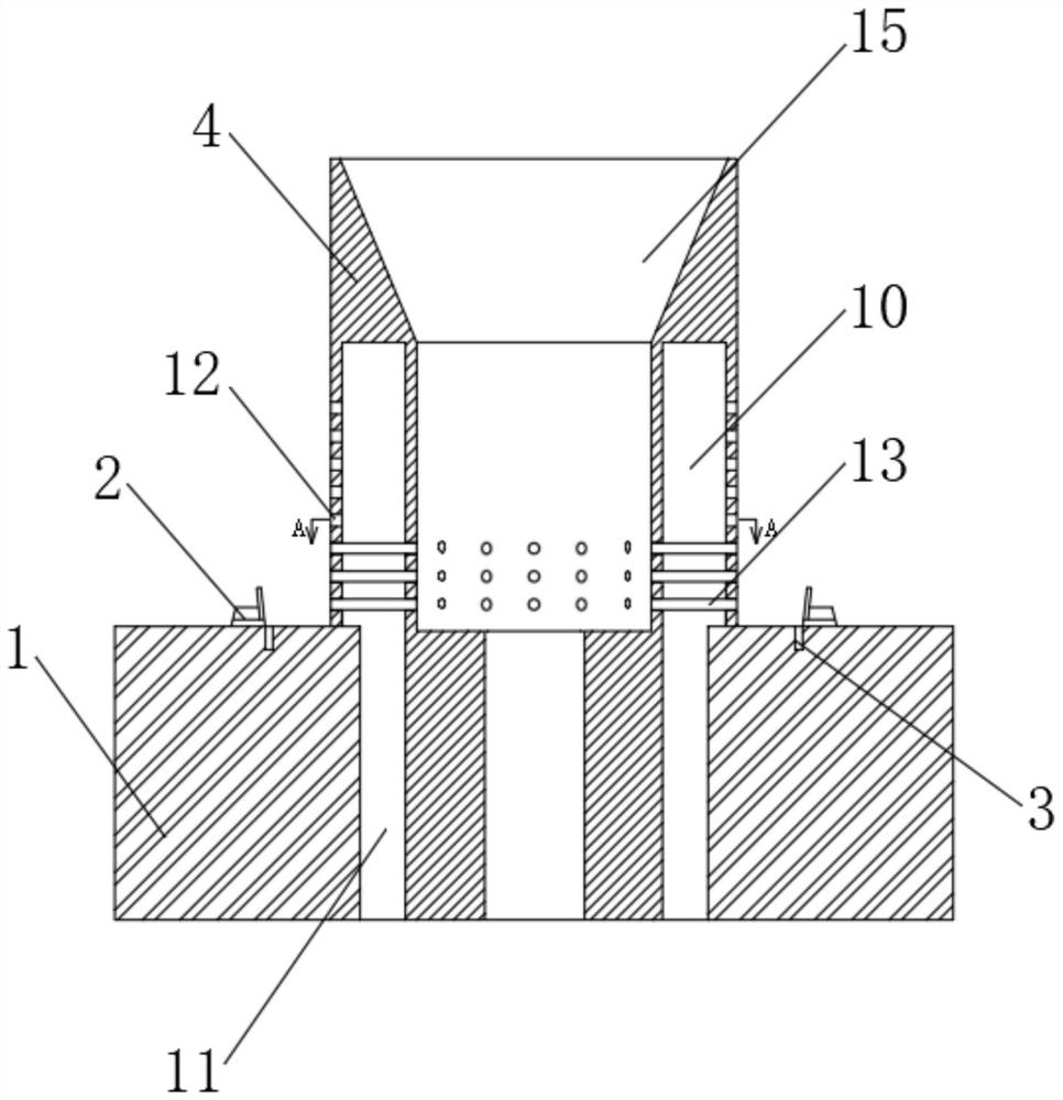
[0019] see Figure 1-3 , a plastic film blowing machine includes a plastic storage platform 1, which stores more plastic slurry, and the temperature of the plastic storage platform 1 reaches 200 degrees Celsius, so that the plastic slurry will not solidify, resulting in the highest temperature at the bottom of the film bubble , the middle of both sides of the upper surface of the plastic storage platform 1 is fixedly equipped with a support seat 2, and the upp...


PUM


Abstract

The invention relates to the technical field of plastic processing, and discloses a plastic film blowing machine. The plastic film blowing machine comprises a plastic storage table, wherein supporting bases are fixedly mounted in the middles of the two sides of the upper surface of the plastic storage table, extrusion openings located in the inner sides of the supporting bases are formed in the upper surface of the plastic storage table, the middle part of the plastic storage table is fixedly sleeved with a die head, and the middle part of the die head is fixedly sleeved with a ventilating pipe. According to the plastic film blowing machine, on one hand, cooling gas gathered at the top is sucked from air suction holes along the outer sides of film bubbles under the suction force of an air suction pipe, on the other hand, large negative pressure is generated in the middle due to spiral airflow generated by oblique arrangement of the air suction holes and the low surrounding temperature of a cooling water pipe, and a part of cooling airflow is sucked in from the interior of a cooling tank, is discharged from communicating pipes after being cooled and directly enters the communicating pipes to be discharged, so that the airflow is the airflow with the lowest temperature when flowing through the bottommost parts of the film bubbles and is directly discharged, the cooling effect of the cooling airflow is improved, and the solidification time of the film bubbles is shortened.

Description

technical field [0001] The invention relates to the technical field of plastic processing, in particular to a plastic film blowing machine. Background technique [0002] Blown film machine is a kind of equipment used to produce plastic film. During the production process, the plastic melt is extruded upward from the circular extrusion port to form a film bubble. The film bubble is pulled and moves upward continuously, and the cooling mechanism continuously blows cooling air to cool the film bubble, so that the film bubble Condensation, and the cooling method mostly chooses internal cooling, and the cooling airflow in the centrifugal direction is blown out from the annular air outlet to cool from the inside of the film bubble. [0003] First of all, when the cooling air is blown out, it first passes through the bottom of the film bubble, then continues to flow upwards, and is finally sucked away from the exhaust pipe, and when the cooling air passes through the position belo...

Claims


Application Information

Patent Timeline
Patent Type & Authority Applications(China)
IPC IPC(8): B29C55/28B29C35/16
CPCB29C35/16B29C55/28B29C2035/1616B29C2035/1658
Inventor 唐集体
Owner 唐集体
Why Eureka
Try Eureka