Food meat roll packaging equipment
A meat roll and equipment technology, which is applied in the field of food meat roll packaging equipment, can solve the problems of inability to adjust the position of a gear lever and to accurately determine the weight of the meat roll, etc.
- Summary
- Abstract
- Description
- Claims
- Application Information
AI Technical Summary
Problems solved by technology
Method used
Image

Examples
specific Embodiment approach 1
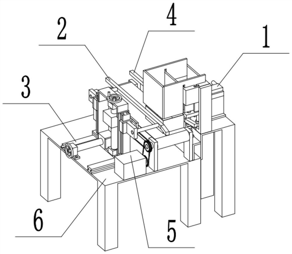
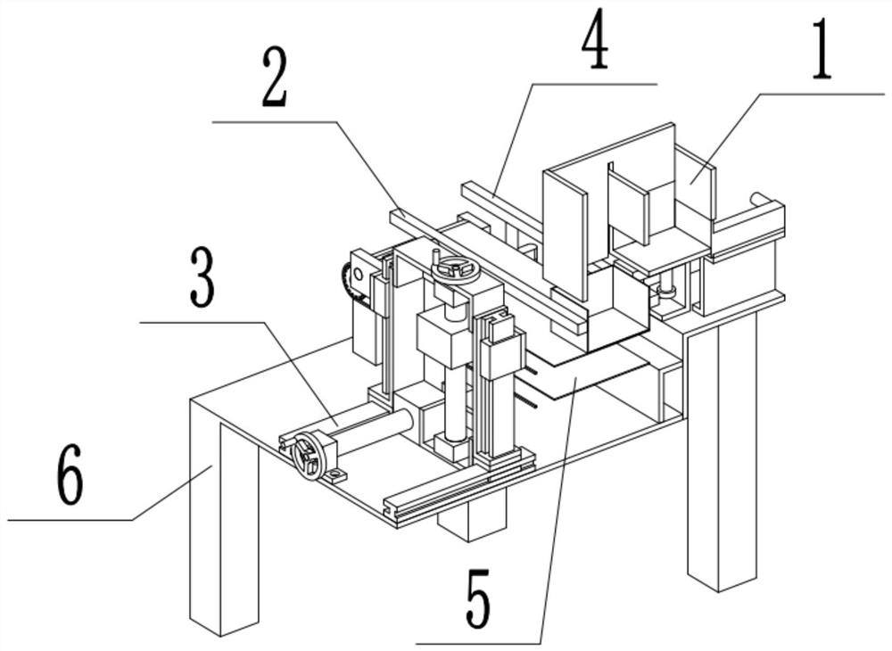
[0043] Combine below Figure 1-24 Describe this embodiment, a food meat roll packaging equipment, including a blanking device 1, an up and down adjustment device 2, a front and rear adjustment device 3, a fixed lever device 4, a feeding device 5, and a base 6. The blanking device 1 and the base 6 are connected, the up and down adjustment device 2 is connected with the front and rear adjustment device 3, the front and rear adjustment device 3 is connected with the base 6, the fixed gear rod device 4 is connected with the base 6, and the feeding device 5 is connected with the base 6.
specific Embodiment approach 2
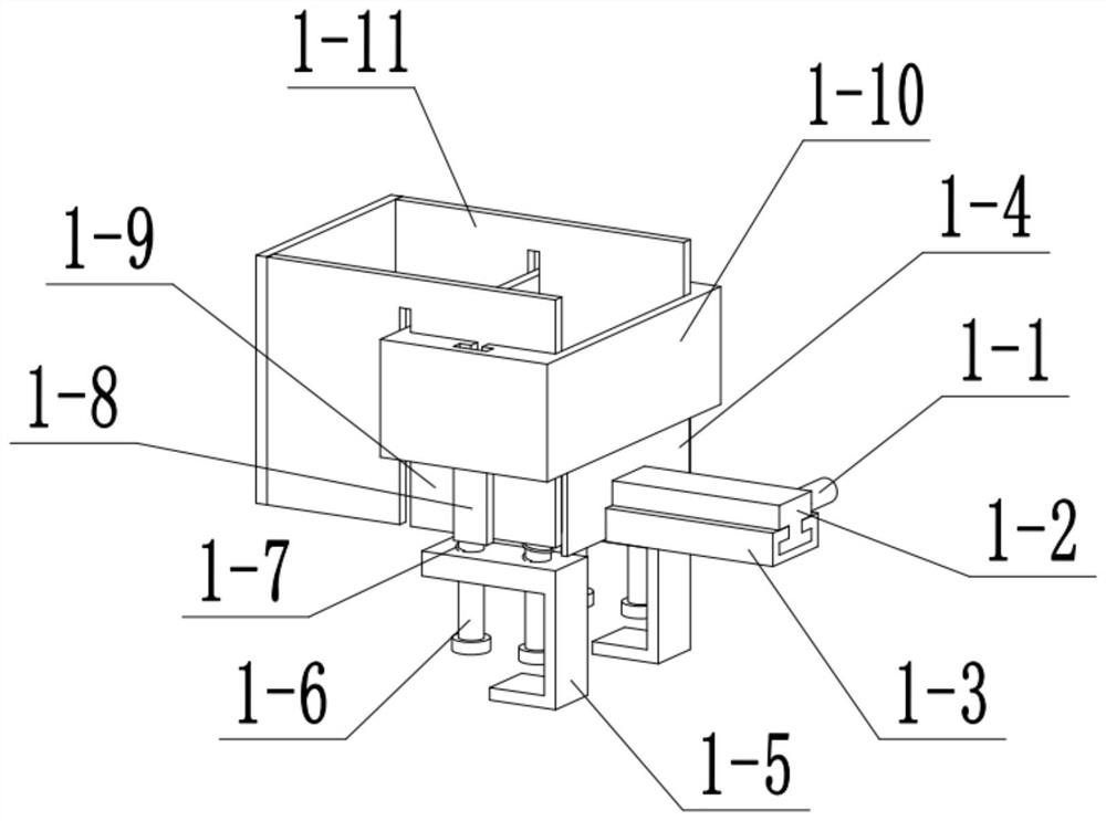
[0045] Combine below Figure 1-24 Describe this embodiment, this embodiment will further explain the first embodiment, the blanking device 1 includes a push handle 1-1, a slider 1-2, a slide rail 1-3, a push plate 1-4, and a support 1 -5. Loading slide bar 1-6, loading spring 1-7, loading slide rail 1-8, loading platform 1-9, blocking frame A1-10, blocking frame B1-11, push handle 1 -1 is welded to the slider 1-2, the slider 1-2 is slidably connected to the slide rail 1-3, the slider 1-2 is welded to the pushing plate 1-4, and the support 1-5 is connected to the material receiving slide bar 1-6 is slidingly connected, the material receiving spring 1-7 is connected with the material receiving slide bar 1-6, the material receiving slide bar 1-6 is welded with the material receiving platform 1-9, and the material receiving slide rail 1-8 is connected with the material receiving Platform 1-9 is welded and connected, material receiving slide rail 1-8 is slidingly connected to mate...
specific Embodiment approach 3
[0048] Combine below Figure 1-24 Describe this embodiment, this embodiment will further explain Embodiment 1. The up and down adjustment device 2 includes an adjustment gear rod 2-1, an adjustment gear rod welding rod 2-2, an adjustment gear rod mounting seat 2-3, and an up and down slider 2-4, upper and lower rails 2-5, mounting seat connecting plate 2-6, vertical bearing seat A2-7, screw rod A2-8, wire sleeve A2-9, rotating handle A2-10, bearing A2-11, The adjusting gear rod 2-1 is welded to the adjusting gear rod welding rod 2-2, the adjusting gear rod welding rod 2-2 is welded to the adjusting gear rod mounting seat 2-3, and the adjusting gear rod mounting seat 2-3 is connected to the upper and lower sliding blocks 2-4 is fixedly connected, the upper and lower sliding blocks 2-4 are slidably connected with the upper and lower sliding rails 2-5, and the adjusting gear lever mounting seat 2-3 and the upper and lower sliding blocks 2-4 are all welded and connected with the m...
PUM
 Abstract
Description
Claims
Application Information
 - R&D
- Intellectual Property
- Life Sciences
- Materials
- Tech Scout
- Unparalleled Data Quality
- Higher Quality Content
- 60% Fewer Hallucinations
Browse by: Latest US Patents, China's latest patents, Technical Efficacy Thesaurus, Application Domain, Technology Topic, Popular Technical Reports.
© 2025 PatSnap. All rights reserved.Legal|Privacy policy|Modern Slavery Act Transparency Statement|Sitemap|About US| Contact US: help@patsnap.com