Airflow dyeing machine nozzle structure capable of improving dyeing efficiency and dyeing machine
An air-flow dyeing machine and nozzle technology, which is used in liquid/gas/steam jet propulsion for fabrics, textile material processing, textile processing machine accessories, etc. The effect of convenience, reducing the possibility of clamping
- Summary
- Abstract
- Description
- Claims
- Application Information
AI Technical Summary
Problems solved by technology
Method used
Image
Examples
Embodiment 1
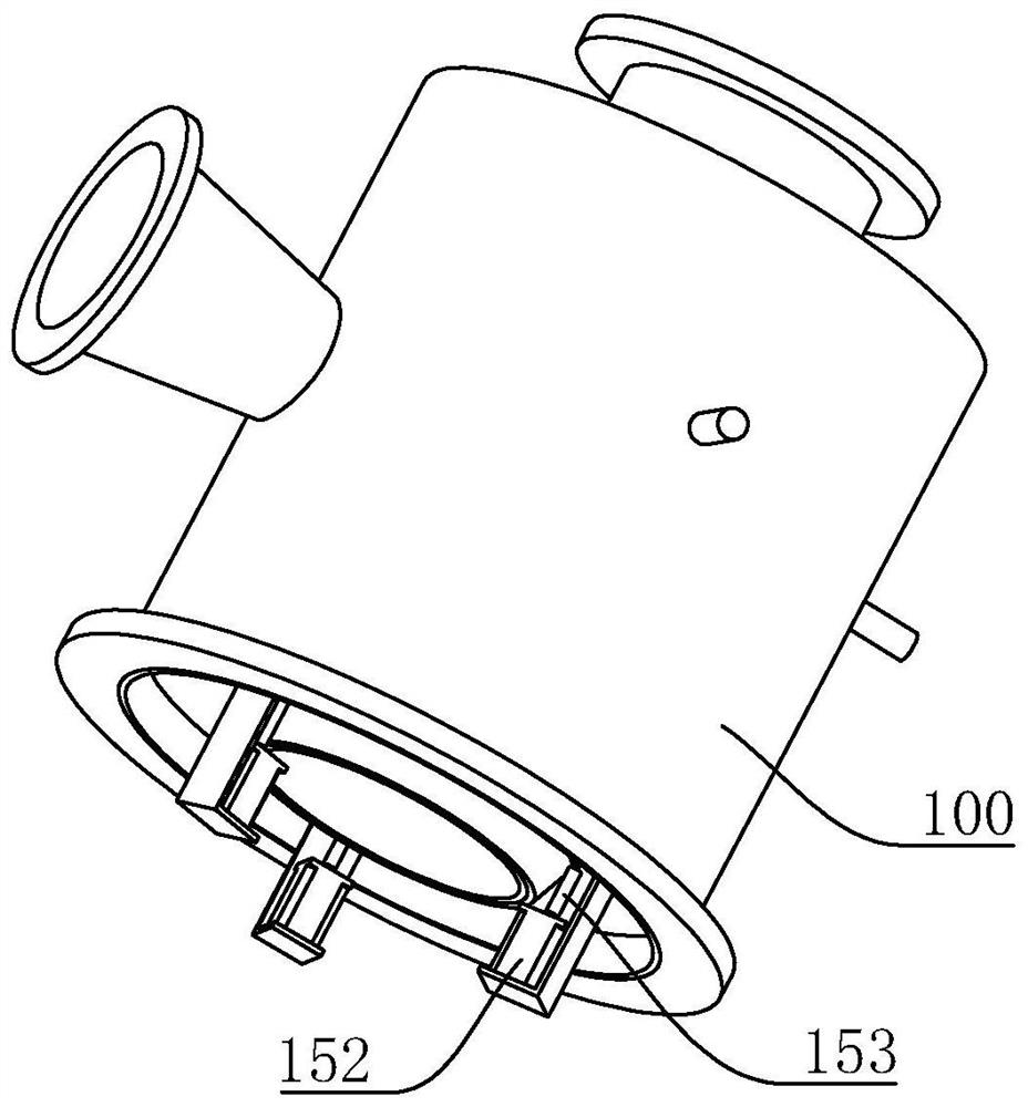
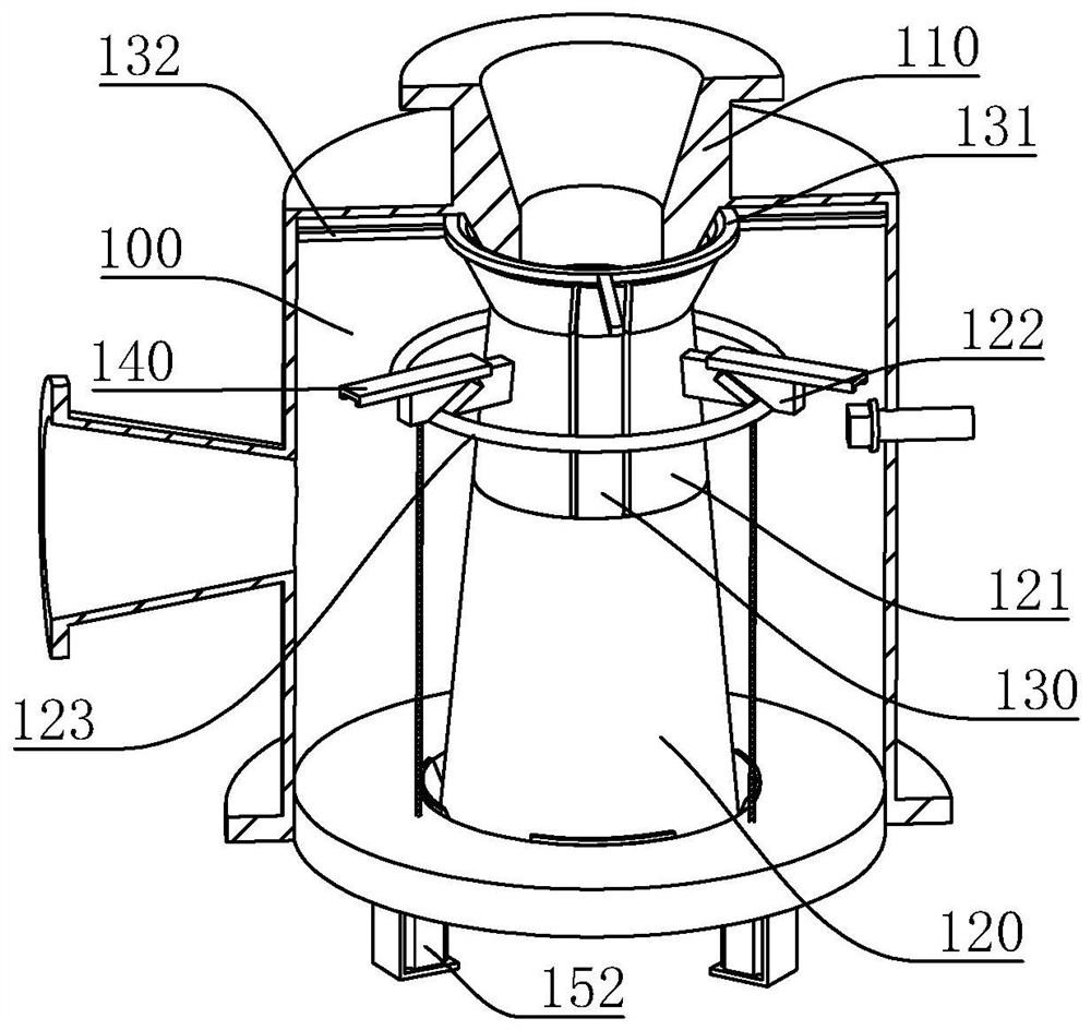
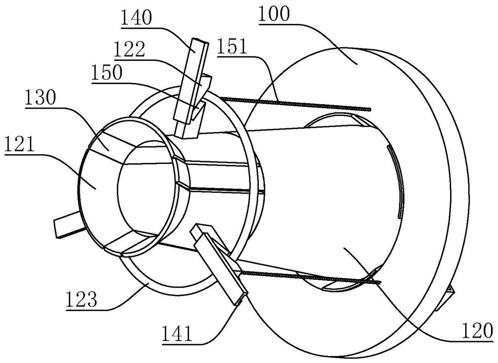
[0039] A nozzle structure of an airflow dyeing machine to improve dyeing efficiency, refer to figure 1 , figure 2 , including a casing 100, an upper nozzle 110 and a lower nozzle fixedly installed in the casing 100 along the moving direction of the cloth. The assembly includes no less than three reducing blocks 121, a connecting piece connected to the reducing block 121 and slidingly connected in the housing 100 in the radial direction, and a driving member arranged in the housing 100 to drive the connecting piece to move . In this embodiment, the inner diameter of the hollow structure formed by the combination of reducing blocks 121 gradually decreases from the side close to the upper nozzle 110 to the other side, and then gradually increases until it is the same as the end of the expanding ring 120 . When the cloth is blocked in the nozzle, the connecting part drives the variable diameter block 121 to move through the driving part, thereby expanding the internal space, fa...
Embodiment 2
[0044] Embodiment 2, the difference with embodiment 1 is that, with reference to Image 6 , the blocking block 130 is slidably connected in the housing 100 in the radial direction, and the outer wall of the blocking block 130 has a resisting block 200, the outer wall of the resisting block 200 can interfere with the driving ring 123, when the driving ring 123 moves in the guide chute 150 so that When each reducing block 121 moves in opposite directions, at the same time, the drive ring 123 interferes with the conflicting block 200 so that each blocking block 130 moves toward each other, and the blocking block 130 can press the cloth towards the middle.
[0045] refer to Image 6 , Figure 7 , the housing 100 is provided with an elastic member for driving the blocking block 130 to reset. In this embodiment, the elastic member is a spring 210, and the connecting ring 131 and the expanding ring 120 are uniformly provided with an extension piece 220 located outside the blocking b...
PUM
 Abstract
Description
Claims
Application Information
 - R&D Engineer
- R&D Manager
- IP Professional
- Industry Leading Data Capabilities
- Powerful AI technology
- Patent DNA Extraction
Browse by: Latest US Patents, China's latest patents, Technical Efficacy Thesaurus, Application Domain, Technology Topic, Popular Technical Reports.
© 2024 PatSnap. All rights reserved.Legal|Privacy policy|Modern Slavery Act Transparency Statement|Sitemap|About US| Contact US: help@patsnap.com


