
Nozzle structure of airflow dyeing machine for improving dyeing efficiency and dyeing machine

An airflow dyeing machine and nozzle technology, which is applied in the direction of liquid/gas/steam jet propulsion fabric, textile material processing, textile processing machine accessories, etc., can solve the problems of fabric dyeing suspension, lower dyeing efficiency, clogging, etc., and achieve dredging mode Convenience and the effect of reducing the possibility of pinching

Active Publication Date: 2022-01-21
浙江紫竹梅印染有限公司
View PDF13 Cites 0 Cited by
  • Summary
  • Abstract
  • Description
  • Claims
  • Application Information

AI Technical Summary

Problems solved by technology

[0004] In view of the related technologies mentioned above, the inventor believes that the inside of the nozzle has a structure of reduced diameter, which causes the cloth to be clogged inside the nozzle with a smaller diameter during the movement, causing the dyeing of the cloth to be suspended, and it needs to be shut down for dredging, which greatly reduces the dyeing effect. efficiency

Method used


Image

  • Nozzle structure of airflow dyeing machine for improving dyeing efficiency and dyeing machine
  • Nozzle structure of airflow dyeing machine for improving dyeing efficiency and dyeing machine
  • Nozzle structure of airflow dyeing machine for improving dyeing efficiency and dyeing machine

Examples


Embodiment 1

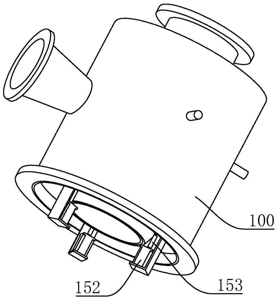
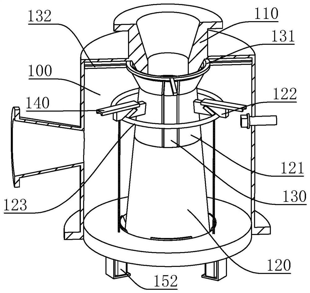
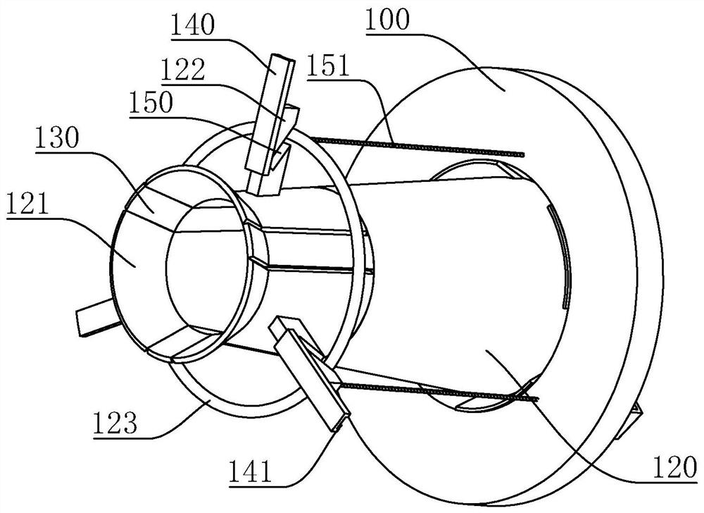
[0039] A nozzle structure of an airflow dyeing machine to improve dyeing efficiency, refer to figure 1 , figure 2 , including a casing 100, an upper nozzle 110 and a lower nozzle fixedly installed in the casing 100 along the moving direction of the cloth. The assembly includes no less than three reducing blocks 121, a connecting piece connected to the reducing block 121 and slidingly connected in the housing 100 in the radial direction, and a driving member arranged in the housing 100 to drive the connecting piece to move . In this embodiment, the inner diameter of the hollow structure formed by the combination of reducing blocks 121 gradually decreases from the side close to the upper nozzle 110 to the other side, and then gradually increases until it is the same as the end of the expanding ring 120 . When the cloth is blocked in the nozzle, the connecting part drives the variable diameter block 121 to move through the driving part, thereby expanding the internal space, fa...

Embodiment 2

[0044] Embodiment 2, the difference with embodiment 1 is that, with reference to Figure 6 , the blocking block 130 is slidably connected in the housing 100 in the radial direction, and the outer wall of the blocking block 130 has a resisting block 200, the outer wall of the resisting block 200 can interfere with the driving ring 123, when the driving ring 123 moves in the guide chute 150 so that When each reducing block 121 moves in opposite directions, at the same time, the drive ring 123 interferes with the conflicting block 200 so that each blocking block 130 moves toward each other, and the blocking block 130 can press the cloth towards the middle.

[0045] refer to Figure 6 , Figure 7 , the housing 100 is provided with an elastic member for driving the blocking block 130 to reset. In this embodiment, the elastic member is a spring 210, and the connecting ring 131 and the expanding ring 120 are uniformly provided with an extension piece 220 located outside the blocking...


PUM


Abstract

This application relates to the technical field of cloth dyeing equipment, and relates to a nozzle structure of an airflow dyeing machine and a dyeing machine that can improve dyeing efficiency. The lower nozzle includes a diameter-reducing assembly and a diameter-expanding ring arranged in sequence along the moving direction of the cloth. The diameter-reducing assembly includes no less than three diameter-reducing blocks, which are connected to the diameter-reducing blocks and are slidably connected in the housing in the radial direction. The connecting piece and the driving piece arranged in the housing are used to drive the connecting piece to move. The application has the following effects: when the cloth is blocked by the nozzle, the connecting part is moved through the driving part, and the connecting part can drive the variable diameter block to move in the radial direction, thereby increasing the inner diameter of the original lower nozzle, so that the blocked cloth can be separated , and after dredging, the variable-diameter block is moved inward, reassembled into the original shape, and then the normal dyeing is carried out, which improves the dyeing efficiency.

Description

technical field [0001] The present application relates to the technical field of cloth dyeing equipment, in particular to an airflow dyeing machine nozzle structure and a dyeing machine that improve dyeing efficiency. Background technique [0002] The air flow dyeing machine generates air flow through the fan to drive the fabric to run. During the dyeing process, the airflow enters the nozzle and the dye liquor delivered by the main pump meets in the nozzle shell, causing the dye liquor to atomize and spray to the fabric passing through the nozzle. Therefore, the fabric can get the best dyeing effect in the dye liquor. The equipment has the advantages of small bath ratio, low cost, less water consumption, energy saving and environmental protection, and has been widely used in the printing and dyeing industry. [0003] The Chinese invention patent with the existing authorized notification number CN101613919B discloses a nozzle of an airflow dyeing machine, which includes a ...

Claims


Application Information

Patent Timeline
Patent Type & Authority Patents(China)
IPC IPC(8): D06B3/28D06B23/00D06B23/04
CPCD06B3/28D06B23/00D06B23/04
Inventor 殷阿四侯铁永殷红生
Owner 浙江紫竹梅印染有限公司
Learn More