
Controllable dedusting environment-friendly unpowered air 1cap

A hood and power technology, which is applied in the field of controllable dust removal, environmental protection and non-powered hood, can solve the problems of blade damage, incomplete repair and maintenance, and hood damage, etc., and achieve the effect of improving the service life

Active Publication Date: 2021-07-09
府谷县昊田煤电冶化有限公司
View PDF7 Cites 2 Cited by
  • Summary
  • Abstract
  • Description
  • Claims
  • Application Information

AI Technical Summary

Problems solved by technology

[0002] Roof unpowered fans are usually installed in warehouses, patios, poultry breeding, greenhouses or mine passages, especially on both sides of the roof ridge of industrial buildings, and use the natural principle of indoor hot air rising and cold air falling to flow through the air. The power generated convects the air inside and outside the room, so as to achieve the purpose of exhausting and ventilating. However, because the unpowered hood is installed on the roof, maintenance and maintenance are very difficult, and the long-term rotation of the hood will cause damage, while the bearing Although it still has the function of ventilation after being damaged, the hood cannot be rotated when it rains, which will cause rain leakage in the side gap of the hood and the blades will be damaged by the wind, and the unpowered hood will easily discharge indoor smoke and dust directly to the outside during ventilation, which greatly affects the outdoors environment, therefore, it is urgent to design a switch-controllable unpowered hood capable of dust removal

Method used


Image

  • Controllable dedusting environment-friendly unpowered air 1cap
  • Controllable dedusting environment-friendly unpowered air 1cap
  • Controllable dedusting environment-friendly unpowered air 1cap

Examples


Embodiment Construction

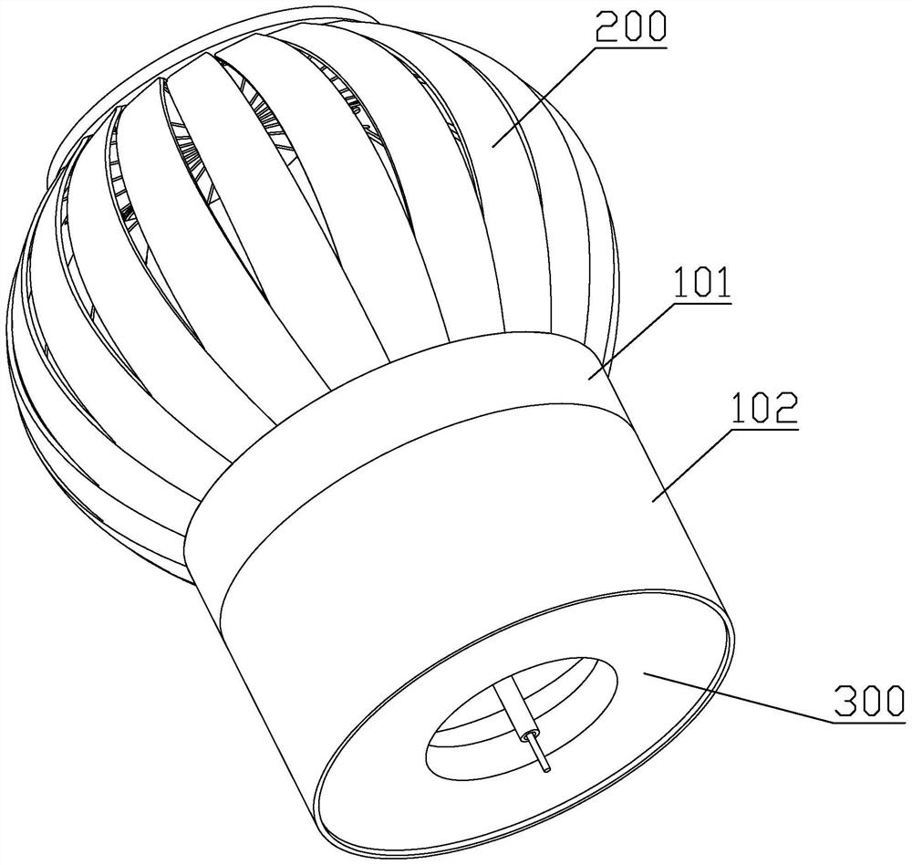
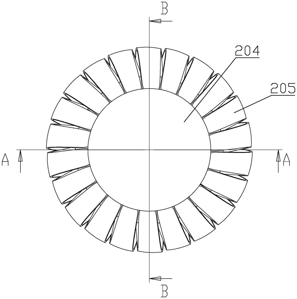
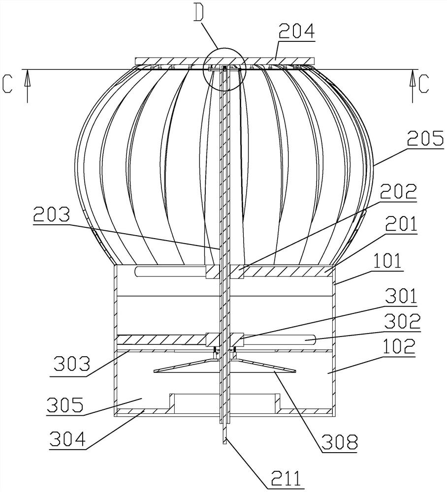
[0024] By the following Figure 1 to 8 The present invention will be described in detail, and the technical solutions of the present invention will become apparent from the embodiments of the present invention, and is merely the embodiments of the invention, not all of the embodiments. Based on the embodiments of the present invention, all other embodiments obtained by those of ordinary skill in the art without making creative labor are in the scope of the present invention.

[0025] The orientation of the following is as follows: The front and back and rear directions of the upper and lower left and right below figure 1 The direction of the front and back and so on the direction of the view direction, figure 1 A front elevational view of the device of the present invention, figure 1 The direction shown is consistent with the front and rear and down directions of the device of the present invention in front of the present invention.

[0026] Such as figure 1 As shown, a controllabl...


PUM


Abstract

The invention belongs to the field of ventilation equipment, and discloses a controllable dedusting environment-friendly unpowered air cap. The cap comprises a cylindrical rotating cylinder, the lower end of the rotating cylinder is rotationally connected with an equal-diameter fixed cylinder, a control device for opening and closing the air cap is arranged on the upper side of the rotating cylinder, and a dust removal device for dust removal during ventilation is arranged in the fixed cylinder. A lifting ring and a sliding pin are arranged, so that when the interior of a plant does not need to be ventilated, a pull rod is pulled downwards through external force, the pull rod pulls the lifting ring to move downwards through a lifting rod, the lifting ring pulls the fan blades through a pull rope to drive the sliding pin to slide in an arc-shaped sliding groove, the fan blades rotate, the gap between the adjacent fan blades is closed, the purpose of stopping rotating for ventilation is achieved, and the service life of a bearing is prolonged.

Description

Technical field [0001] The invention belongs to the field of ventilation, in particular, involving a controlled type dust-free environmentally friendly electric cap. Background technique [0002] Roof-free fan is usually installed in a warehouse, patio, poultry breeding, flower house or mine channel, especially installed on both sides of the ridge of the industrial roof, and uses the natural principles of the indoor hot air flow, cold air declines, through air flow The generated power causes the air inside and outside to form the air, and the purpose of ventilation ventilation is achieved, but the inactive housing is very unwarable due to its installation and maintenance on the roof, and the wind is long-term rotation leads to damage, while bearings After the damage, it also has a ventilated function, but the wind cap cannot rotate when it rains, can cause the wind cap to leak the rain and the blade is damaged by wind, and the no power hood is easy to discharge out of the indoor ...

Claims


Application Information

Patent Timeline
IPC IPC(8): E04D13/17B01D45/18B01D45/08
CPCE04D13/17B01D45/18B01D45/08Y02E10/72
Inventor 吴常欢
Owner 府谷县昊田煤电冶化有限公司
Learn More