
High-universality reduction gearbox special for draught fan

A universal, reduction box technology, which is applied to the components of pumping devices for elastic fluids, mechanical equipment, machines/engines, etc., can solve the problem that lubrication technology cannot change the lubrication effect, reduce the efficiency of lubricating oil use, and increase gear wear and other problems, to achieve the effect of compact structure, improved cleaning performance and improved stability

Inactive Publication Date: 2021-07-09
ZHEJIANG JINGXING GEARED MOTOR
View PDF5 Cites 1 Cited by
  • Summary
  • Abstract
  • Description
  • Claims
  • Application Information

AI Technical Summary

Problems solved by technology

[0002] The reduction box is generally used for low-speed and high-torque transmission equipment. The motor, internal combustion engine or other high-speed operating power is decelerated through the gear with a small number of teeth on the input shaft of the reduction box and the large gear on the output shaft to achieve the purpose of deceleration; Different application scenarios have different operation effects on the structure of the gears inside the reduction box. Generally, when lubricating the inside of the fan-specific reduction box, pour the lubricating oil into the lubrication box, and carry out all the gears through the drive of the gears. Lubrication; however, this method reduces the use efficiency of the lubricating oil, and at the same time, due to the special application environment, it will be mixed with impurities; through this method of lubrication, the impurities washed down by the lubricating oil will be driven to the gear by the rotation of the gear again , which will increase the gear wear; at the same time, the gear speed will change when the gearbox is running, but the existing lubrication technology cannot change the lubrication effect with the change of the gear speed

Method used


Image

  • High-universality reduction gearbox special for draught fan
  • High-universality reduction gearbox special for draught fan
  • High-universality reduction gearbox special for draught fan

Examples


Embodiment Construction

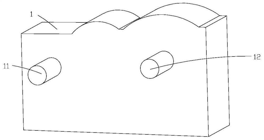
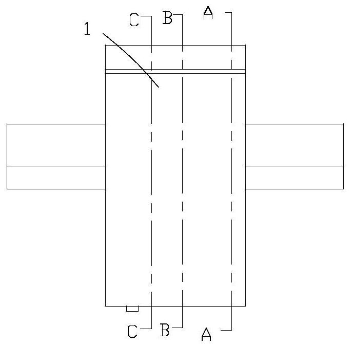
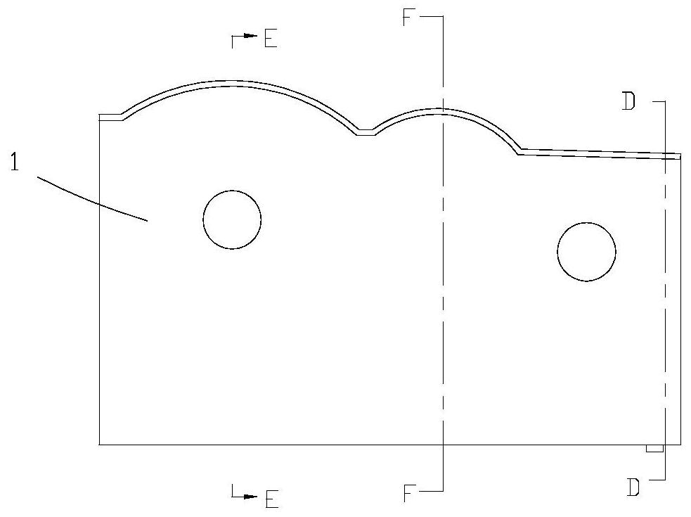
[0041] like Figure 1-22 As shown, a special reduction box for fans with strong versatility includes a main body 1, a driving wheel 11, a reduction wheel 12, an oil storage chamber 13, a filter device 2, a driving wheel 3, and a lubricating device 4; the filter device 2 includes a partition Plate 21, guide hole 22, filter block 23, filter hole 24, filter spring 25, stationary plate 26, louver plate 27, convection hole 28, cleaning mechanism 5; the driving wheel 11 is rotatably embedded in the main body 1; The deceleration wheel 12 is rotatably embedded in the main body 1 and engages with the driving wheel 11; the oil storage cavity 13 is set in the main body 1; the filter device 2 is set in the oil storage cavity 13; The driving wheel 3 is rotatably embedded in the main body 1 and meshes with the reduction wheel 12; the partition plate 21 is arranged in the oil storage chamber 13; Evenly arranged; the longitudinal section of the filter block 23 is arc-shaped, and is movably e...


PUM


Abstract

The invention discloses a high-universality reduction gearbox special for a draught fan. The high-universality reduction gearbox special for the draught fan comprises a main body, a driving wheel, a speed reduction wheel, an oil storage cavity, a filtering device, a driving wheel and a lubricating device. The filtering device comprises a partition plate, flow guide holes, a filtering block, filtering holes, filtering springs, a static plate, louver boards, convection holes and a cleaning mechanism. According to the high-universality reduction gearbox special for the draught fan, lubricating oil is sprayed to the driving wheel and the speed reduction wheel in a spraying mode through the lubricating device to achieve lubricating and cooling, and the using effect of the lubricating oil is improved; and impurities in the lubricating oil are cleaned away through the cleaning mechanism when the reduction gearbox operates, on one hand, the application effect of the lubricating oil is improved, on the other hand, the rotating stability of the driving wheel and the speed reduction wheel can be improved, the universality of the reduction gearbox is further improved, and the application effect of the reduction gearbox is more stable.

Description

technical field [0001] The invention belongs to the field of reduction boxes, in particular to a special reduction box for fans with high versatility. Background technique [0002] The reduction box is generally used for low-speed and high-torque transmission equipment. The motor, internal combustion engine or other high-speed operating power is decelerated through the gear with a small number of teeth on the input shaft of the reduction box and the large gear on the output shaft to achieve the purpose of deceleration; Different application scenarios have different operation effects on the structure of the gears inside the reduction box. Generally, when lubricating the inside of the fan-specific reduction box, pour the lubricating oil into the lubrication box, and carry out all the gears through the drive of the gears. Lubrication; however, this method reduces the use efficiency of the lubricating oil, and at the same time, due to the special application environment, it will...

Claims


Application Information

Patent Timeline
Patent Type & Authority Applications(China)
IPC IPC(8): F16H57/04F04D29/06
CPCF16H57/0404F16H57/0456F16H57/0435F16H57/0465F16H57/0408F04D29/063
Inventor 张明军陈庆舍叶芬芬郭岳军王仲华
Owner ZHEJIANG JINGXING GEARED MOTOR
Learn More