
Air flow detection method

A technology of air flow and detection method, applied in the aerospace field, can solve the problems of instability, detection variability, aircraft airflow detection and calibration, etc., and achieve the effects of high detection accuracy, convenient use, and reduction of the influence of gravity

Active Publication Date: 2021-07-09
WUCHANG UNIV OF TECH
View PDF7 Cites 0 Cited by
  • Summary
  • Abstract
  • Description
  • Claims
  • Application Information

AI Technical Summary

Problems solved by technology

[0004] In the process of aerospace, whether it is an aircraft, a space shuttle or even a spacecraft, it needs to be isolated and sealed from the inside and outside to prevent gas leakage from causing danger. Therefore, it is necessary to effectively monitor the airflow inside the aircraft in real time, but the attitude of the aircraft itself is not stable, so The airflow detection in the aircraft cannot be calibrated relying on the direction of gravity, resulting in detection variability and instability

Method used


Image

  • Air flow detection method

Examples


Embodiment

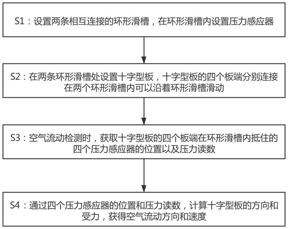
[0028] Example: such as figure 1 As shown, it is only one of the embodiments of the present invention, an air flow detection method, comprising the following steps:

[0029] S1: Set two interconnected annular chutes, and set pressure sensors in the annular chutes;

[0030] Here, when step S1 is performed, the two annular sliding grooves include a first groove and a second groove, and the first groove and the second groove are connected to each other and arranged perpendicular to each other.

[0031] Of course, when step S1 is executed, the pressure sensor is electrically connected to the control terminal connected to the gyroscope of the aircraft.

[0032] S2: Set cross-shaped plates at the two annular chutes, and the four plate ends of the cross-shaped plates are respectively connected in the two annular chutes and can slide along the annular chutes;

[0033] Similarly, when step S2 is performed, the cross-shaped board includes a first board and a second board, the middle p...


PUM


Abstract

The invention provides an air flow detection method, and relates to the technical field of aerospace, and the method comprises the following steps that S1, two annular sliding grooves which are connected with each other arearranged, and pressure sensors are arranged in the annular sliding grooves; s2, a cross-shaped plate is arranged at the two annular sliding grooves, and the four plate ends of the cross-shaped plate are connected into the two annular sliding grooves correspondingly and can slide along the annular sliding grooves; s3, during air flow detection, the positions and pressure readings of the four pressure sensors abutting against the four plate ends of the cross-shaped plate in the annular sliding groove are obtained; s4, the direction and stress of the cross-shaped plate are calculated through the positions and pressure readings of the four pressure sensors, and the air flowing direction and speed are obtained. The air flow detection method is convenient to use, air flow in all directions is effectively detected, so that the air tightness in the aircraft is monitored, the gravity influence when the flight attitude of the aircraft changes can be reduced, the detection precision is high, and the air flow detection method is suitable for air flow detection in various aircrafts.

Description

technical field [0001] The invention relates to the field of aerospace technology, [0002] In particular, the present invention relates to an air flow detection method. Background technique [0003] The development of the aerospace industry is the result of the rapid progress of science and technology and the rapid development of social production in the 20th century. The achievements of aerospace have concentrated many new achievements in science and technology. Aerospace activities so far, although they are only the first few steps away from the cradle of the earth, their effects have gone far beyond the field of science and technology, and have had extensive and far-reaching impacts on the economy and human social life. [0004] In the process of aerospace, whether it is an aircraft, a space shuttle or even a spacecraft, it is necessary to isolate and seal the inside and outside to prevent gas leakage from causing danger. Therefore, it is necessary to effectively monit...

Claims


Application Information

Patent Timeline
Patent Type & Authority Applications(China)
IPC IPC(8): G01M3/26G01D21/02
CPCG01M3/26G01D21/02
Inventor 安庆原菊蒲李凤旭贺照云
Owner WUCHANG UNIV OF TECH
Learn More