Portable lubricating oil filtering device

A filter device and lubricating oil technology, applied in the direction of filtration separation, mobile filter element filter, separation method, etc., can solve the problems of reducing filtration efficiency, clogging of composite filter elements, etc., and achieve the goals of reducing air pressure, improving service life, and reducing use costs Effect

Active Publication Date: 2021-07-13
李新
View PDF17 Cites 0 Cited by
  • Summary
  • Abstract
  • Description
  • Claims
  • Application Information

AI Technical Summary

Problems solved by technology

[0004] The purpose of the present invention is to overcome the problems in the prior art and provide a portable lubricating oil filter device that can vibrate the composite filter element when the lubricating oil is filtered, thereby avoiding impurities from adhering to the composite filter element and causing the composite filter element to be blocked. Reduce filtration efficiency and other issues

Method used


Image

  • Portable lubricating oil filtering device
  • Portable lubricating oil filtering device

Examples


Embodiment 1

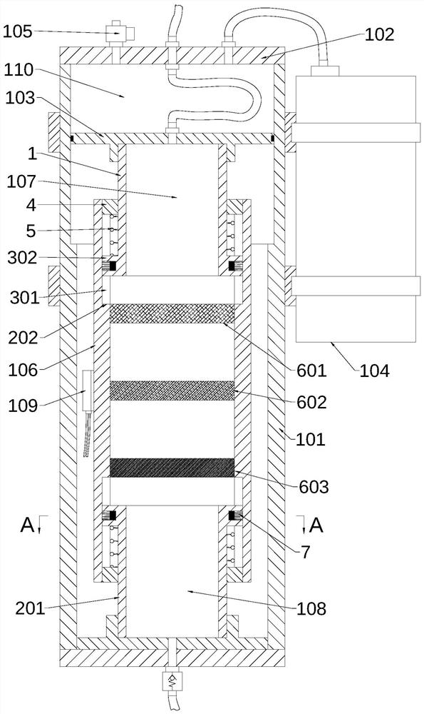
[0023] Such as figure 1 and 2 As shown, a portable lubricating oil filter device provided by the present invention includes: an outer piston cylinder, a filter cylinder and a vibration generator 109, the outer piston cylinder includes an outer cylinder body 101, an outer cylinder cover 102 and a linkage piston 103, and the outer piston cylinder The top opening of the cylinder body 101 is sealed and fixedly connected with the outer cylinder head 102. The outer cylinder head 102 is provided with an air inlet and an exhaust port. The air inlet is connected with an air source device 104, and the air source device 104 is electrically connected There is a controller, the controller is electrically connected to a power supply device, the exhaust port is connected to an electromagnetic switch valve 105, the electromagnetic switch valve 105 is electrically connected to the controller, and one end of the linkage piston 103 is connected to the top of the outer cylinder body 101 The inne...

Embodiment 2

[0028] On the basis of Embodiment 1, in order to prevent the vibration generated by the vibration generator 109 from being transmitted to the outer cylinder 101 through the filter cylinder 106, thereby effectively reducing the noise generated when the device is in operation.

[0029] Such as figure 1 As shown, wherein, a filter cylinder piston 201 is also provided between the filter cylinder body 106 and the outer cylinder body 101, one end of the filter cylinder piston 201 is fixedly connected to the bottom inner wall of the outer cylinder body 101, and the other end of the filter cylinder piston 201 is connected to the inner wall of the bottom of the outer cylinder body 101. The bottom inner wall of the filter cylinder 106 is sealed and slidingly connected, and the top and bottom inner walls of the filter cylinder 106 are provided with a limit spacer 202, and the limit spacer 202 at the top of the filter cylinder 106 is used to limit the movement of the linkage piston. 103, ...

Embodiment 3

[0032] On the basis of Embodiment 2, in order to prevent the vibration generated by the vibration generator 109 from causing the filter cylinder 106 to rotate and cause the pipeline to be entangled.

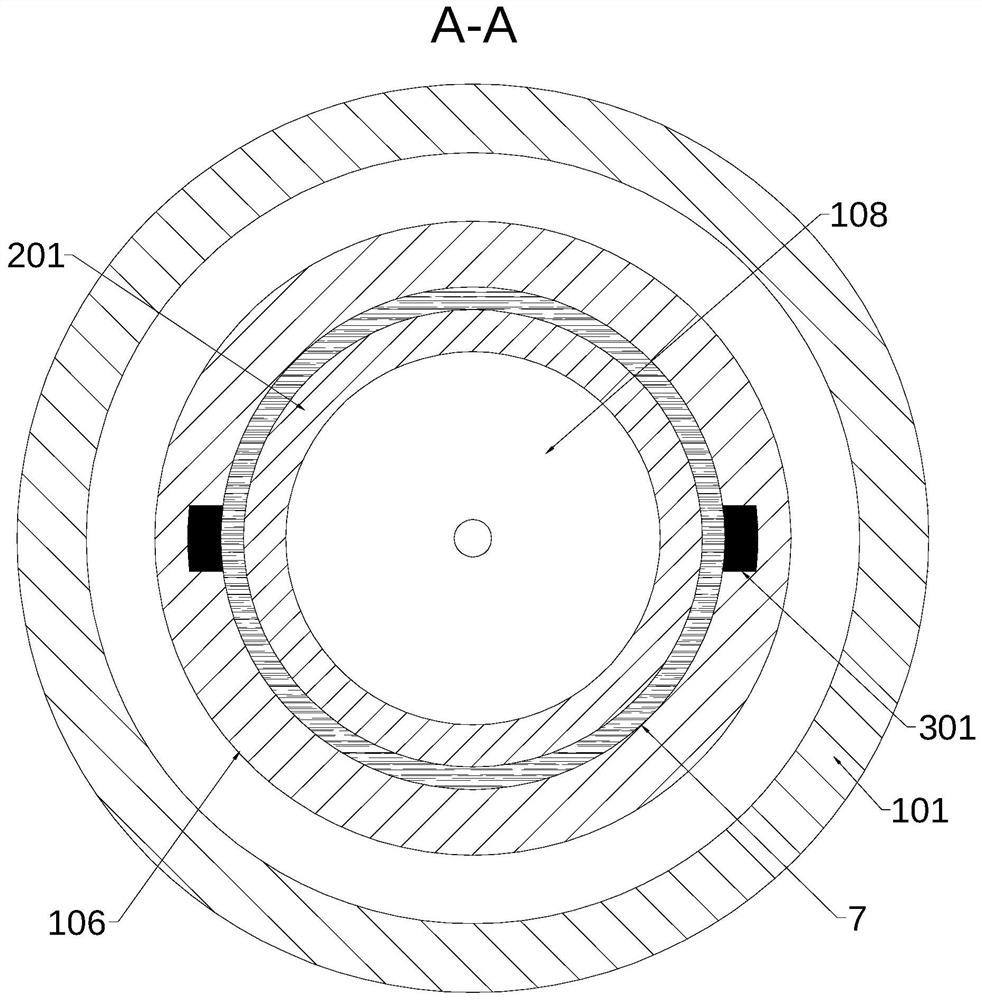
[0033] Such as figure 1 and 2As shown, wherein, the top inner wall and the bottom inner wall of the filter cylinder 106 are provided with a guide groove 301 along the axial direction of the filter cylinder 106, and the linkage piston 103 and the filter cylinder piston 201 are both provided with a guide block 302. The guide block 302 of the piston 103 is in sealing and sliding connection with the guide groove 301 on the top inner wall of the filter cylinder body 106 , and the guide block 302 of the filter cylinder piston 201 is in sealing and sliding connection with the guide groove 301 on the inner wall at the bottom end of the filter cylinder body 106 .

[0034] By setting the guide block 302 and the guide groove 301, the linkage piston 103 and the filter cylinder piston 201 ca...


PUM


Abstract

The invention discloses a portable lubricating oil filtering device, and belongs to the technical field of filtering equipment. The portable lubricating oil filtering device comprises an outer piston cylinder, a filter cylinder and a vibration generator; the outer piston cylinder comprises an outer cylinder body, an outer cylinder cover and a linkage piston; the outer cylinder cover is provided with an air inlet and an air outlet, the air inlet is communicated with an air source device, the air outlet is communicated with an electromagnetic switch valve, and one end of the linkage piston is in sealed sliding connection with the inner wall of the top end of the outer cylinder body; the filter cylinder comprises a filter cylinder body and a composite filter element, the inner wall of the top end of the filter cylinder body is in sealed sliding connection with the linkage piston, an inner cavity of the filter cylinder body is divided into an upper cavity and a lower cavity by the composite filter element, and the upper cavity is communicated with an oil pump; and the vibration generator is fixedly connected to the outer wall of the filter cylinder body. According to the portable lubricating oil filtering device, when lubricating oil is filtered, the composite filter element is vibrated, so that the situation that the composite filter element is blocked and the filtering efficiency is reduced due to the fact that impurities are attached to the composite filter element is avoided.

Description

technical field [0001] The invention relates to the technical field of filtering equipment, in particular to a portable lubricating oil filtering device. Background technique [0002] Lubricating oil is often used on mechanical equipment to lubricate, cool and prevent rust on mechanical parts. However, lubricating oil will be doped with a large amount of impurities during long-term use, which will affect the quality of lubrication. Therefore, lubricating oil needs to be filtered or replaced in time after being used for a period of time. [0003] When the existing lubricating oil filter device is filtering the lubricating oil, impurities in the lubricating oil are easy to adhere and accumulate on the filter element, resulting in clogging of the filter element, reducing the filtering efficiency and increasing the difficulty of filtering. Contents of the invention [0004] The purpose of the present invention is to overcome the problems in the prior art and provide a portabl...

Claims


Application Information

Patent Timeline
IPC IPC(8): B01D33/42B01D33/54B01D33/80
CPCB01D33/42B01D33/54B01D33/80
Inventor 李新
Owner 李新
Why Eureka
Try Eureka