
Garden pool cleaning device

A technology for cleaning devices and pools, used in water supply devices, waterway systems, cleaning hollow objects, etc., can solve problems such as a lot of manpower and material resources, time-consuming, low efficiency, etc., and achieve efficient cleaning, labor saving, and improving cleaning efficiency. Effect

Active Publication Date: 2021-07-13
南通诺熙机械科技有限公司
View PDF9 Cites 2 Cited by
  • Summary
  • Abstract
  • Description
  • Claims
  • Application Information

AI Technical Summary

Problems solved by technology

[0004] The existing cleaning method is to collect pebbles together, and manually clean the pebbles and the pool floor. The cleaning efficiency is low. After cleaning, the pebbles are spread on the surface of the pool. Cleaning requires a lot of manpower and material resources. time

Method used


Image

  • Garden pool cleaning device
  • Garden pool cleaning device
  • Garden pool cleaning device

Examples


Embodiment 1

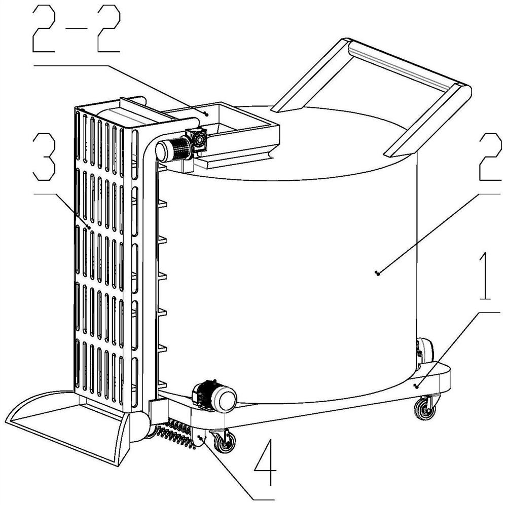
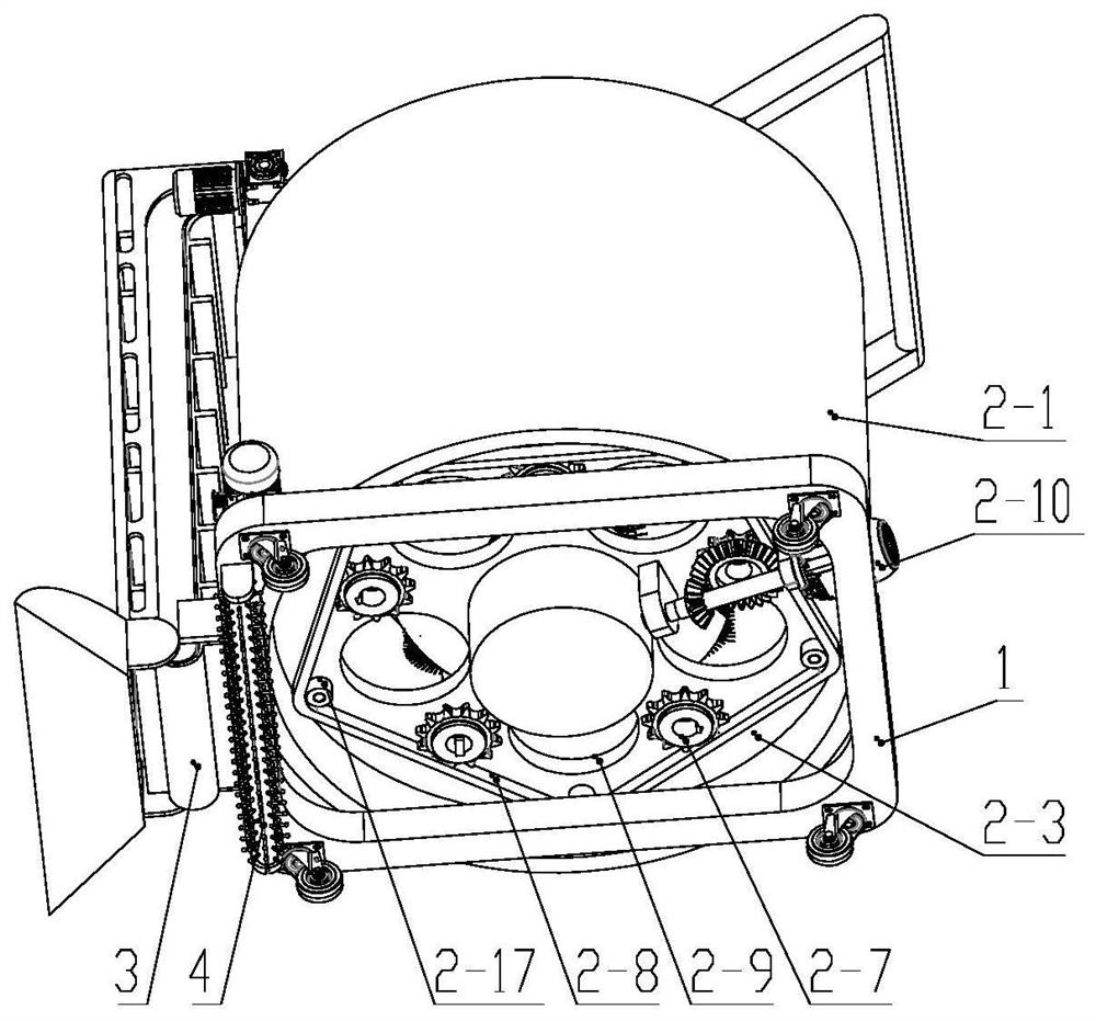
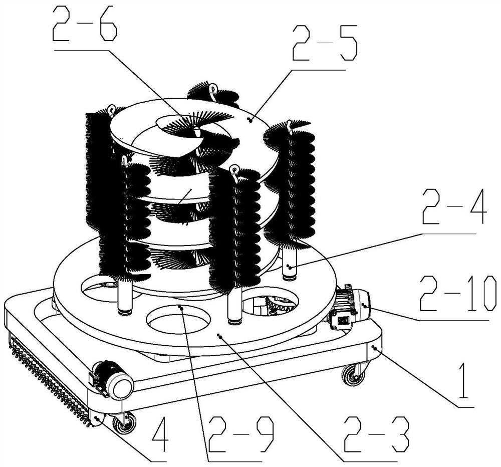
[0035] see Figure 1 to Figure 6 , the present invention provides a garden pool cleaning device, comprising an underframe 1, the four corners below the underframe 1 are respectively provided with universal casters, the universal casters are convenient for the movement of the device, the convenience of the lifting device is used, and the underframe 1 A cleaning mechanism 2 for cleaning pebbles is arranged above, and a conveying mechanism 3 for collecting pebbles is arranged on one side of the cleaning mechanism 2. The inlet end of the conveying mechanism 3 is located below the chassis 1, and the other end is an outlet end, which extends to The top of the cleaning mechanism 2;

[0036] It also includes a cleaning mechanism 4 for cleaning the bottom of the garden pool, and the cleaning mechanism 4 is located under the chassis 1;

[0037] Cleaning mechanism 2 comprises shell 2-1 that is fixedly arranged with underframe 1, and the upper end of shell 2-1 is provided with feed port ...

Embodiment 2

[0062] On the basis of Embodiment 1, the outer diameter of the rotating shaft in the middle of the roller brush 2-6 is slightly smaller than the inner diameter of the shaftless auger 2-5, and the thicker rotating shaft can reduce the number of roller brushes 2-6 and the shaftless auger 2. The gap between -5 is to avoid the pebbles in cleaning from falling from the gap between the shaftless auger 2-5 and the roller brush 2-6, thereby affecting the cleaning mechanism 2 to perform cleaning work.

Embodiment 3

[0064] On the basis of embodiment 1, the lower end of the roller brush 2-6 is provided with a tapered guide plate, the guide plate is coaxial with the rotation axis of the roller brush 2-6, and the lower end of the guide plate and the upper surface of the lower baffle plate 2-3 Sliding connection, pebbles fall from the gap between the shaftless auger 2-5 and the roller brush 2-6 and then slide through the guide plate into the feeding hole 2-9, avoiding the accumulation of pebbles on the lower baffle 2-3 Cleaning mechanism 2 is not working properly.


PUM


Abstract

The invention discloses a garden pool cleaning device, and relates to the field of garden equipment. According to the technical scheme, the garden pool cleaning device comprises a bottom frame, wherein universal caster are arranged at the four corners of the lower portion of the bottom frame, the universal casters facilitate movement of the device, the use convenience of the device is improved, a cleaning mechanism used for cleaning cobblestones is arranged above the bottom frame, a conveying mechanism used for collecting the cobblestones is arranged on one side of the cleaning mechanism, the inlet end of the conveying mechanism is located below the bottom frame, the other end of the conveying mechanism is an outlet end, and the outlet end extends to the position above the cleaning mechanism; and the garden pool cleaning device further comprises a sweeping mechanism used for sweeping the bottom of a garden pool and located below the bottom frame. The garden pool cleaning device has the beneficial effects that labor is saved, the cleaning steps are simplified, the cleaning efficiency is improved, and moss on the surfaces of the cobblestones is efficiently cleaned; and the structure is simple and use is convenient.

Description

technical field [0001] The invention relates to the field of garden equipment, in particular to a garden pool cleaning device. Background technique [0002] In the current garden design, it is usually based on the design of adding water features to the garden design, including pools, fountains, waterfalls and other shapes. In the design of water features, pebbles are an indispensable landscaping element, usually at the bottom of the pool Lay with pebbles or use pebbles for styling around a water feature. [0003] Since the water in the pool is basically internally circulated, moss is attached to the bottom of the pool and the surface of the pebbles. Too much moss will affect the waterscape shape; Clean up, including removing moss from cobblestone surfaces as well as moss from pool floors. [0004] The existing cleaning method is to collect pebbles together, and manually clean the pebbles and the pool floor. The cleaning efficiency is low. After cleaning, the pebbles are sp...

Claims


Application Information

Patent Timeline
Patent Type & Authority Applications(China)
IPC IPC(8): B08B9/087B08B3/02B08B1/02B08B13/00E03F7/00B08B1/20
CPCB08B9/087B08B3/022B08B13/00E03F7/00B08B1/12B08B1/20B08B1/32
Inventor 隋承昊
Owner 南通诺熙机械科技有限公司
Learn More