
Novel die-cutting machine

A die-cutting machine, a new type of technology, applied in the direction of presses, forming tools, mechanical equipment, etc., can solve the problems of cumbersome operation, time-consuming, large driving output power, etc., and achieve the effect of simple operation

Active Publication Date: 2021-07-13
FOSHAN TIANZHENG MASCH CO LTD
View PDF19 Cites 4 Cited by
  • Summary
  • Abstract
  • Description
  • Claims
  • Application Information

AI Technical Summary

Problems solved by technology

[0002] At present, the existing die-cutting machine adopts two main methods for adjusting the distance between the cutter and the backing plate: one is manual adjustment, and the operator adjusts the four columns of the cutter mechanism one by one, However, the operation of this adjustment method is very cumbersome and time-consuming; the other type is automatic adjustment. The motor of the cutter adjustment mechanism rolls through the drive belt and pulley, and the four columns are driven by the belt and pulley to rotate axially, so that the cutter The knife is lifted up and down to adjust the distance between the cutter and the backing plate. Although this method can overcome the cumbersome operation defects of the traditional manual adjustment method, the drive output power of the motor is generally relatively large, and it is difficult to control the column. Small range of rotation, therefore, this method is only suitable for rough adjustment of the distance between the cutter and the backing plate, if applied to fine adjustment, it is easy to cause over-adjustment, so that the die-cutting process is prone to damage to the knife or The problem of incomplete die cutting

Method used


Image

  • Novel die-cutting machine
  • Novel die-cutting machine
  • Novel die-cutting machine

Examples


Embodiment Construction

[0026] In order to make the purpose, technical solutions and advantages of the present invention clearer, the present invention will be further described in detail below in conjunction with the examples and accompanying drawings. As a limitation of the present invention.

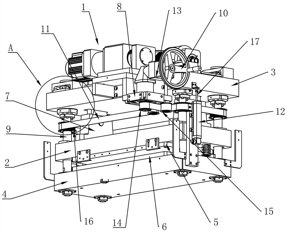
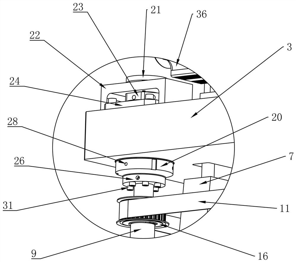
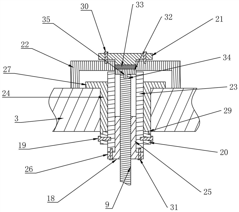
[0027] Figure 1-Figure 7 Shows the specific structure of a new type of die-cutting machine in an embodiment of the present invention, including a lifting mechanism 1, an adjustment mechanism, a movable mold base 2, an upper mold base 3 and a lower mold base 4, and the bottom of the movable mold base 2 is installed There is a cutter 5, the top of the lower mold base 4 is equipped with a backing plate 6 that cooperates with the cutter 5, the lifting mechanism 1 is installed on the top of the upper mold base 3, and the lifting mechanism 1 is installed on the top of the upper mold base 3. On the top of the upper mold base 3, the lifting arm 7 of the lifting mechanism 1 passes through the upper mold base 3 and ...


PUM


Abstract

The invention provides a novel die-cutting machine which comprises an adjusting mechanism, a movable die holder provided with a cutter, an upper die holder provided with a lifting mechanism, and a lower die holder provided with a base plate. A lifting arm of the lifting mechanism penetrates through the upper die holder so as to be fixedly connected with the movable die holder; the adjusting mechanism comprises a guide screw rod, a hand-cranking wheel, a first belt, an electronic ruler and a speed reducer; the speed reducer is connected with the hand-cranking wheel; the lower end of the guide screw rod is rotationally connected with the lower die holder; the upper end of the guide screw rod penetrates through the movable die holder and is matched with the upper die holder; a tensioning wheel is arranged at the bottom of a supporting frame provided with the speed reducer; an output shaft of the speed reducer penetrates through the supporting frame and is sleeved with a driving wheel; the guide screw rod is externally and fixedly sleeved with a first roller; the driving wheel, the tensioning wheel and the first roller are connected through the belt; and a pull rod of the electronic ruler is connected with the upper die holder. Compared with the prior art, the novel die-cutting machine provided by the invention is easy to operate, and the distance between the cutter and the base plate can be precisely and finely adjusted.

Description

technical field [0001] The invention relates to the technical field of die-cutting machine manufacturing, in particular to a novel die-cutting machine. Background technique [0002] At present, the existing die-cutting machine adopts two main methods for adjusting the distance between the cutter and the backing plate: one is manual adjustment, and the operator adjusts the four columns of the cutter mechanism one by one, However, the operation of this adjustment method is very cumbersome and time-consuming; the other type is automatic adjustment. The motor of the cutter adjustment mechanism rolls through the drive belt and pulley, and the four columns are driven by the belt and pulley to rotate axially, so that the cutter The knife is lifted up and down to adjust the distance between the cutter and the backing plate. Although this method can overcome the cumbersome operation defects of the traditional manual adjustment method, the drive output power of the motor is generally ...

Claims


Application Information

Patent Timeline
Patent Type & Authority Applications(China)
IPC IPC(8): B21D28/02B21D37/04B21D55/00B26F1/40B26D7/26B26D7/22B30B15/00B30B15/02F16P1/02
CPCB21D28/02B21D37/04B21D55/00B26F1/40B26D7/2628B26D7/22B30B15/0029B30B15/02F16P1/02Y02P70/10
Inventor 劳英姿邱旺郁
Owner FOSHAN TIANZHENG MASCH CO LTD
Learn More