Front passenger car and front floor framework thereof

A front floor and bus technology, applied to the upper structure of the bus, vehicle parts, upper structure sub-assembly, etc., can solve the driver's safety threat and other issues

Active Publication Date: 2021-07-13
ZHENGZHOU YUTONG BUS CO LTD
View PDF5 Cites 0 Cited by
  • Summary
  • Abstract
  • Description
  • Claims
  • Application Information

AI Technical Summary

Problems solved by technology

[0004] The purpose of the present invention is to provide a front floor frame of a front passenger car, in order to solve the problem that the front floor frame of a front passenger car in the prior art is in a frontal collision accident, and the floor frame at the driver's footrest is relative to the driver's foot. The floor frame at the step is "turned forward", which poses a threat to the safety of the driver. Another purpose of the present invention is to provide a front-mounted passenger car to solve the front-mounted passenger car in the prior art when a frontal collision accident occurs. , the floor frame at the driver's pedal is "turned forward" relative to the floor frame at the driver's pedal, which poses a threat to the safety of the driver

Method used


Image

  • Front passenger car and front floor framework thereof
  • Front passenger car and front floor framework thereof
  • Front passenger car and front floor framework thereof

Examples


Embodiment 2

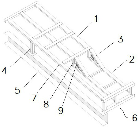
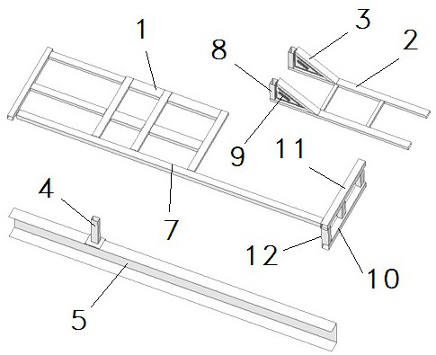
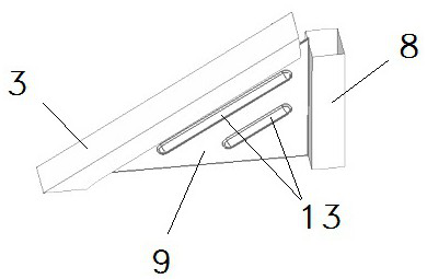
[0071] The specific embodiment 2 of the front floor frame of the front passenger car of the present application: the difference between this embodiment and the embodiment 1 is that no erecting load-bearing members and force-transmitting longitudinal beams are provided, and the oblique connecting beams and stress dispersing plates are dispersed and connected. The stress at the beam, the stress dispersing structure consists only of connecting vertical beams and stress dispersing plates.

specific Embodiment 3

[0072] The specific embodiment 3 of the front floor frame of the front passenger car of the present application: the difference between this embodiment and the embodiment 1 is that the connecting vertical beams and the stress dispersing plates are not provided, and the vertical load-bearing members and the force-transmitting longitudinal beams are dispersed to connect the inclined beams. The stress at the beam, the stress dispersion structure is only composed of the vertical bearing member and the force transmission longitudinal beam.

specific Embodiment 4

[0073] The specific embodiment 4 of the front floor frame of the front passenger car of the present application: the difference between this embodiment and the embodiment 1 is that no connecting vertical beams are provided, and the oblique connection is dispersed by means of the vertical load-bearing members, the force-transmitting longitudinal beams and the stress dispersion plate. stress on the beam.


PUM


Abstract

The invention relates to a front passenger car and a front floor framework thereof. The front floor framework of the front passenger car comprises a first part and a second part, and the first part is provided with a seat installation area used for installing a seat fixing frame of a driver seat; a second part which corresponds to a pedal of a driver, and the first part is higher than the second part and located behind the second part; and a connecting oblique beam, wherein the upper end of the connecting oblique beam is fixedly connected with the front end part of the first part, and the lower end is fixedly connected with the second part; a front floor framework of the front passenger car is provided with a stress dispersion structure, and when the front passenger car is collided in the forward direction, the stress dispersion structure can disperse stress at the connecting oblique beam. The stress dispersion structure can disperse stress borne by the connecting oblique beam when the front passenger car is collided in the forward direction, deformation of the connecting oblique beam and the connecting position of the front floor framework and the connecting oblique beam is well avoided, and therefore the problem that the first part is turned forwards and the safety of a driver is affected due to the fact that deformation is combined with inertia moment is well avoided.

Description

technical field [0001] The present invention relates to a front passenger car and its front floor frame. Background technique [0002] The front passenger car refers to the passenger car with the front engine. In order to facilitate the driver's entry and exit, the front passenger car usually has a driver's door corresponding to the driver's seat. Different from the common rear-mounted passenger cars, the front floor frame of the front passenger car is a non-planar structure. The specific reason for this is that the floor frame at the fixed position of the seat is restricted by the tire directly below, and the position needs to be set higher and higher. Can not be lowered; in order to facilitate the driver to get on and off the car from the driver's door, and to ensure that there is a suitable height difference between the driver's footrest and the driver's seat, the floor frame of the driver's footrest is low and cannot be increased. The front floor frame of the passenger ...

Claims


Application Information

Patent Timeline
IPC IPC(8): B62D25/20B62D31/02
CPCB62D25/20B62D25/2054B62D25/2018B62D31/02
Inventor 武帅京崔崇桢管国朋刘刚邵海洋聂宝佳
Owner ZHENGZHOU YUTONG BUS CO LTD
Why Eureka
Try Eureka