Laminating device and method applied to large-size battery assembly

A technology for battery components and lamination devices, applied in the direction of lamination devices, lamination, electrical components, etc., can solve problems that affect battery components and pass rate, single cell increase, hidden cracks, etc., to reduce lamination Fragments and hidden cracks, improving efficiency and pass rate, buffering the effect of impact

Pending Publication Date: 2019-10-25
DONGFANG HUANSHENG PHOTOVOLTAIC (JIANGSU) CO LTD
View PDF0 Cites 3 Cited by
  • Summary
  • Abstract
  • Description
  • Claims
  • Application Information

AI Technical Summary

Problems solved by technology

[0002] During the lamination process of solar cell components, due to thermal expansion and contraction, the thermal expansion mismatch of various materials will lead to chip fragmentation or cracking, affecting cell components and yield
In order to improve the efficiency of solar cell components, large-sized silicon wafers can be used to make solar cell components. The increase in the surface area of ​​a single cell can significantly increase the effective area of ​​solar cell components, increase the conversion rate of the battery, and thereby increase the power of the components; but Large-sized cells are more likely to be unevenly stressed during the lamination process, and are more prone to cracks and cracks during the rapid cooling process, which reduces the qualified rate of modules

Method used


Image

  • Laminating device and method applied to large-size battery assembly
  • Laminating device and method applied to large-size battery assembly

Examples


Embodiment 1

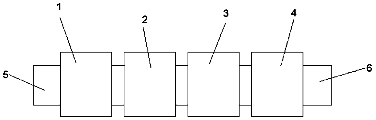
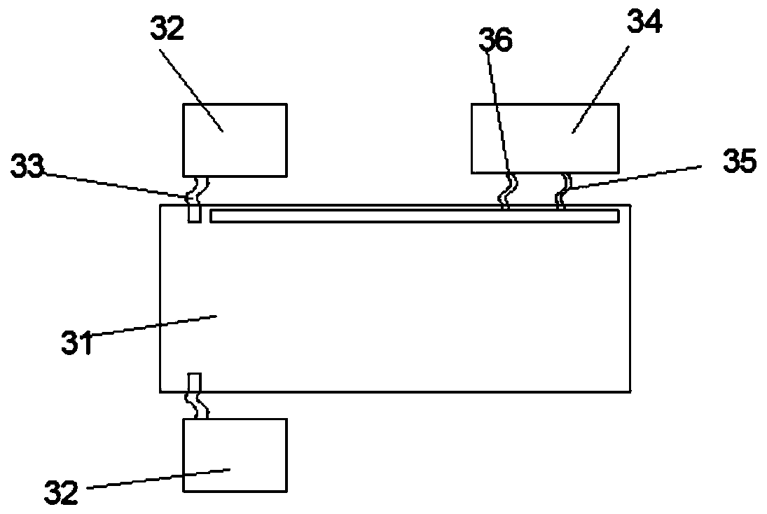
[0045] A lamination device applied to large-sized battery components, including a sequentially connected feeding table 5, a lamination chamber 1, a curing chamber 2, a pre-cooling chamber 3, a cooling chamber 4, and a discharge table 6, and the inside of the pre-cooling chamber 3 The temperature is 50-80°C, and the temperature in the cooling chamber 4 is 20-50°C. The pre-cooling chamber 3 and the cooling chamber 4 have the same structure; the pre-cooling chamber 3 includes a pre-cooling chamber 31, a refrigerator 34 and a vacuum pump 32, and the vacuum pump 32 communicates with the pre-cooling chamber 31 through a vacuum tube 33, and the pre-cooling chamber 31 is provided with a cooling chamber. The water circulation pipeline is specifically a cooling plate with a cavity inside. The cavity in the cooling plate is bent and arranged in a pipeline type. The water inlet pipe 35 and the water outlet pipe 36 at both ends of the cooling water circulation pipeline in the form of a cool...

Embodiment 2

[0048] A lamination device applied to large-sized battery components, comprising a sequentially connected feeding table 5, a lamination chamber 1, a curing chamber 2, a pre-cooling chamber 3, a cooling chamber 4, and a discharge table 6, and the pre-cooling chamber 3 includes For the first pre-cooling chamber and the second pre-cooling chamber, the temperature in the first pre-cooling chamber is 65-80°C, the temperature in the second pre-cooling chamber is 50-65°C, and the temperature in the cooling chamber 4 is 20-50°C. The structure of the first pre-cooling chamber, the second pre-cooling chamber and the cooling chamber 4 are the same; the structure of the cooling chamber 4 in the existing three-cavity automatic laminator can be adopted, and the temperature sensing device and the cooling device in each chamber are controlled by cooperation The temperature of each chamber. The lamination chamber 1 and the curing chamber 2 can also adopt the same structure as in the three-cavi...

Embodiment 3

[0050] A lamination method applied to large-scale battery components, including four steps of lamination, curing, pre-cooling and cooling. Firstly, the battery components are made by lamination and curing. Lower the component temperature to 50-80°C, and lower the component temperature to 20-50°C during the cooling phase.

[0051] The specific operation steps are as follows:

[0052] Step 1 Transfer the components into the lamination chamber, heat up to 130-160°C under vacuum, and laminate the components with a silica gel plate after the POE melts, keep the lower chamber evacuated, and place for lamination for 5-10 minutes;

[0053] Step 2: Transfer the component to the curing chamber, keep it in a vacuum environment at 130-160°C for curing, keep the lower chamber in vacuum, and keep curing for 5-10 minutes;

[0054] Step 3 Transfer the components to the pre-cooling chamber, keep the pre-cooling chamber at 50-80°C for pre-cooling, keep the lower chamber vacuumed, and keep the ...


PUM


Abstract

The invention relates to a laminating device and method applied to a large-size battery assembly. The laminating device comprises a laminating cavity, a curing cavity, pre-cooling cavities and a cooling cavity which are connected sequentially, and the temperature in the pre-cooling cavities is higher than the temperature in the cooling cavity; and in the laminating process, the assembly is sequentially subjected to the four steps of laminating, curing, pre-cooling and cooling, wherein in the pre-cooling process, the assembly is cooled from 130-160 DEG C to 50-80 DEG C firstly and then placed into the cooling cavity to be cooled to 20-50 DEG C. The laminating device and method have the beneficial effects that the laminating device including the one or more pre-cooling cavities is adopted, through a stepped cooling method, the influences of quick cooling on large-size battery pieces are reduced, stress, caused by thermal expansion and cold contraction phenomena in the cooling process, ofthe surface of a silicon wafer is dispersed, impact borne by the surfaces of the battery pieces is buffered, the phenomena of laminating fragments and subfissure of the battery pieces are obviously reduced, the efficiency of assembly preparation is improved, and the qualified rate of assembly preparation is increased.

Description

technical field [0001] The invention belongs to the technical field of photovoltaics, and in particular relates to a lamination device and a lamination method applied to large-scale battery components. Background technique [0002] During the lamination process of solar cell components, due to thermal expansion and contraction, the mismatch of thermal expansion of various materials will lead to chip fragmentation or cracking, affecting cell components and yield. In order to improve the efficiency of solar cell components, large-sized silicon wafers can be used to make solar cell components. The increase in the surface area of ​​a single cell can significantly increase the effective area of ​​solar cell components, increase the conversion rate of the battery, and thereby increase the power of the components; but Large-sized cells are more likely to be unevenly stressed during the lamination process, and are more prone to cracks and cracks during the rapid cooling process, whi...

Claims


Application Information

Patent Timeline
IPC IPC(8): B32B37/10B32B37/08H01L31/048H01L31/18
CPCB32B37/1018B32B37/08H01L31/048H01L31/18Y02E10/50
Inventor 桂军王岩
Owner DONGFANG HUANSHENG PHOTOVOLTAIC (JIANGSU) CO LTD
Why Eureka
Try Eureka