
Electric pole correction device for electric power engineering

A technology for electric power engineering and electric poles, which is applied in the field of electric pole correction devices for electric power engineering, and can solve the problems of reducing the stability of electric poles, unable to adjust, and insufficient stability.

Pending Publication Date: 2021-07-13
沈婷园
View PDF5 Cites 3 Cited by
  • Summary
  • Abstract
  • Description
  • Claims
  • Application Information

AI Technical Summary

Problems solved by technology

[0004] Although the equipment in the above-mentioned patents can fix the electric pole during correction, since both types of equipment use hoops or arc-shaped plate devices to fix the electric pole when correcting the electric pole inside, although they can fix the electric pole However, due to the strength of the hoop and the arc-shaped plate itself and the small stress area on the electric pole, the above-mentioned device has insufficient stability for fixing the electric pole when the electric pole is corrected, and at the same time The above-mentioned patent number is: the patent document of CN202010637156.6. When the patent document limits the position of the electric pole, the internal fixing plate and the connecting plate are all fixed structures, which cannot be adjusted. When fixing, there may be gaps left on both sides of the pole, which reduces the stability of the subsequent position limit of the pole, so there is an urgent need for a pole correction device for electric power engineering to solve the above existing problems

Method used


Image

  • Electric pole correction device for electric power engineering
  • Electric pole correction device for electric power engineering
  • Electric pole correction device for electric power engineering

Examples


Embodiment Construction

[0034] The following will clearly and completely describe the technical solutions in the embodiments of the present invention with reference to the accompanying drawings in the embodiments of the present invention. Obviously, the described embodiments are only some, not all, embodiments of the present invention. Based on the embodiments of the present invention, all other embodiments obtained by persons of ordinary skill in the art without making creative efforts belong to the protection scope of the present invention.

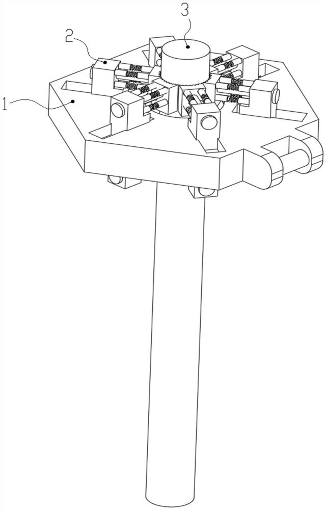
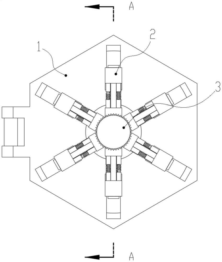
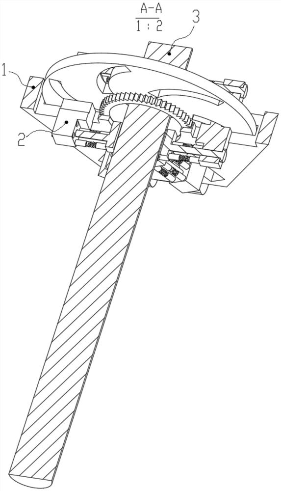
[0035] see Figure 1-7 , an embodiment provided by the present invention: a pole correction device for electric power engineering, including an adjustment mechanism 1, a limit mechanism 2 and a pole 3,

[0036]The inner end surface of the adjustment mechanism 1 is evenly and equidistantly slidingly clamped with six sets of limit mechanisms 2 for positioning, and the inner end surface of the limit mechanism 2 is movably clamped with a pole 3,

[0037] The posi...


PUM


Abstract

The invention discloses an electric pole correcting device for electric power engineering. The device comprises an adjusting mechanism, limiting mechanisms and an electric pole; the inner end face of the adjusting mechanism is evenly, equidistantly and slidably connected with the six sets of limiting mechanisms for positioning in a clamped mode; and the electric pole is movably connected with the inner end faces of the limiting mechanisms in a clamped mode. According to the electric pole correcting device for electric power engineering, by arranging the adjusting mechanism, during correction, a fixed motor can provide enough power for rotation of a guide disc through a connecting gear, and meanwhile, when the guide disc rotates, limiting displacement can be conducted on the limiting mechanisms through six sets of guide grooves at the same time, so that the six sets of limiting mechanisms can conduct centrifugal or centripetal displacement at the same time. Therefore, the follow-up adjusting mechanism can conveniently control the limiting mechanisms to stably limit the electric poles with different radiuses, the adaptability of the device is improved, and meanwhile the stability of limiting the electric poles is also improved.

Description

technical field [0001] The invention relates to the technical field of electric power engineering equipment, in particular to a pole straightening device for electric power engineering. Background technique [0002] The patent number is CN202010637156.6, which discloses a pole straightening device for electric power engineering, which belongs to the field of auxiliary equipment for electric power engineering. An arc-shaped plate, slide grooves are provided on the opposite surfaces of the connecting plates on both sides, the first slider and the second slider are slidably connected to the slide grooves on both sides, and the second arc-shaped slider is hinged on the first slider. plate, the second slider is provided with a fixing piece for fixing the edge of the second arc-shaped plate away from the first slider to the second slider, and the connecting plates on both sides are provided for driving the first slider and the second slider. The two sliders are located in the chu...

Claims


Application Information

Patent Timeline
IPC IPC(8): E04H12/34
CPCE04H12/345
Inventor 沈婷园
Owner 沈婷园
Learn More