Ignition equipment and device and ignition control method

A technology of ignition equipment and ignition device, applied in the field of electronics, can solve the problems of relay not having self-detection on-off state, difficult to be found, damage to ignition clip and device to be ignited, etc.

Pending Publication Date: 2021-07-13
SHENZHEN BASEUS TECH CO LTD
View PDF0 Cites 0 Cited by
  • Summary
  • Abstract
  • Description
  • Claims
  • Application Information

AI Technical Summary

Problems solved by technology

[0003] However, the relays used in the existing ignition clips are all standard general-purpose products. The disadvantage of this kind of relay is that the moving contacts are easy to stick to the shell during use so that the contacts cannot be disconnected, and the relay itself does not have the ability to self-detect the on-off state. Function
This makes the existing protective structure of the ignition clip prone to failure and difficult to be found, easily leading to ignition failure, and damage to the ignition clip and the device to be ignited

Method used


Image

  • Ignition equipment and device and ignition control method
  • Ignition equipment and device and ignition control method
  • Ignition equipment and device and ignition control method

Examples


Embodiment 1

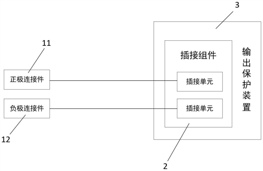
[0049] See attached figure 1 , the ignition device of the present invention includes a positive connector 11 , a negative connector 12 , a detection module, a plug assembly 2 , a control module and an output protection device 3 . Among them, the plug-in assembly 2 includes more than two plug-in units, and the positive connector 11 and the negative connector 12 are respectively electrically connected to the corresponding plug-in units; the output protection device 3 includes a housing and a mechanical drive structure arranged inside the housing. , the housing is provided with an opening corresponding to the plug-in assembly 2 . Specifically, the plug assembly 2 can be a plug assembly, the positive connector 11 and the negative connector 12 are respectively electrically connected to the corresponding plug unit, and the mechanical driving structure is used to drive the plug assembly or the housing to move, so that the plug assembly is exposed from the opening or Income housing. ...

Embodiment 2

[0056] This embodiment provides an ignition device, which includes the ignition device described in Embodiment 1 and an external power supply. The external power supply is provided with an output terminal corresponding to the plug-in assembly 2 of the ignition device. When the ignition device of this embodiment is used for ignition, the positive connector 11 and the negative connector 12 are connected to the device to be ignited, the detection module performs voltage detection, and the MCU judges whether the ignition device is reversed or short-circuited according to the voltage, and the display module The detected voltage data, the polarity of the device to be ignited connected to the positive connector 11 and the negative connector 12 and the judgment result of the MCU are displayed.

[0057] The initial state of the plug assembly 2 and the output protection device 3 is that the plug assembly is in the housing of the output protection device 3 or the initial state of the sock...

Embodiment 3

[0068] This embodiment provides an ignition control method, using the ignition device described in Embodiment 1 for ignition. See attached Figure 16 , the specific workflow of this method is as follows:

[0069] After the positive connection piece 11 and the negative connection piece 12 are connected to the device to be ignited, the detection information of the detection module is acquired. Wherein, the detection information includes information such as the magnitude of the voltage, the polarity of the device to be ignited connected to the positive connector 11 and the negative connector 12 .

[0070] Judging whether the connection polarity of the positive connector 11 and the negative connector 12 on the device to be ignited is correct, the control module controls the mechanical drive structure to adjust the state of the output protection device 3, including: the plug-in assembly 2 can under the first preset condition Plugged with an external power supply; the plug assembl...


PUM


Abstract

The invention provides ignition equipment. The equipment comprises a positive electrode connecting piece, a negative electrode connecting piece and a plug-in assembly, the plug-in assembly comprises two or more plug-in units, and the positive electrode connecting piece and the negative electrode connecting piece are electrically connected with the corresponding plug-in units respectively; an output protection device comprises a shell and a mechanical driving structure arranged in the shell; a detection module is used for detecting whether the connection polarity of the positive electrode connecting piece and the negative electrode connecting piece on the to-be-ignited device is correct or not, if the connection polarity is correct, the condition is a first preset condition, and if the connection polarity is incorrect, the condition is a second preset condition; and a control module is used for driving the mechanical driving structure to output mechanical motion, so that the plug-in assembly can be plugged with an external power supply under the first preset condition and cannot be plugged with the external power supply under the second preset condition. An ignition device can be connected with the external power source only when the ignition equipment is correctly connected with the automobile power source, and damage to an ignition clamp and the automobile power source due to wrong connection is avoided.

Description

technical field [0001] The invention relates to the field of electronic technology, in particular to an ignition device, a device and an ignition control method. Background technique [0002] Cars usually use their own battery to ignite and start, but in daily life, improper operation often occurs after parking, such as forgetting to turn off the lights, etc., resulting in the situation that the ignition device cannot be ignited and started until the power of the ignition device is exhausted. Therefore, ignition clips for emergency ignition of automobiles have appeared on the market to meet user needs. Usually, a detection module and a relay are installed in the device, and the control circuit is disconnected when a reverse connection of the line is detected. [0003] However, the relays used in the existing ignition clips are all standard general-purpose products. The disadvantage of this kind of relay is that the moving contacts are easy to stick to the shell during use so...

Claims


Application Information

Patent Timeline
Patent Type & Authority Applications(China)
IPC IPC(8): F02P17/00F02P3/04
CPCF02P3/04F02P17/00
Inventor 何世友
Owner SHENZHEN BASEUS TECH CO LTD
Why Eureka
Try Eureka