Cage for rolling bearing and rolling bearing

A rolling bearing and cage technology, applied in the field of cages, can solve the problems that the cage does not utilize high speed and high load, the axial beam of the cage is broken, and the cage is melted, etc., so as to prevent excessive compression or tension, prevent high speed and High load, reduced tangential load effect

Pending Publication Date: 2021-07-13
SCHAEFFLER TECH AG & CO KG
View PDF2 Cites 0 Cited by
  • Summary
  • Abstract
  • Description
  • Claims
  • Application Information

AI Technical Summary

Problems solved by technology

Therefore, the cage, especially the plastic cage, is prone to breakage of the cage, especially the axial beam, under the working conditions of high speed and severe load environment, and the melting of the cage will occur in more severe cases.
Therefore, current cages do not take advantage of high-speed and high-load conditions

Method used


Image

  • Cage for rolling bearing and rolling bearing
  • Cage for rolling bearing and rolling bearing

Examples


Embodiment Construction

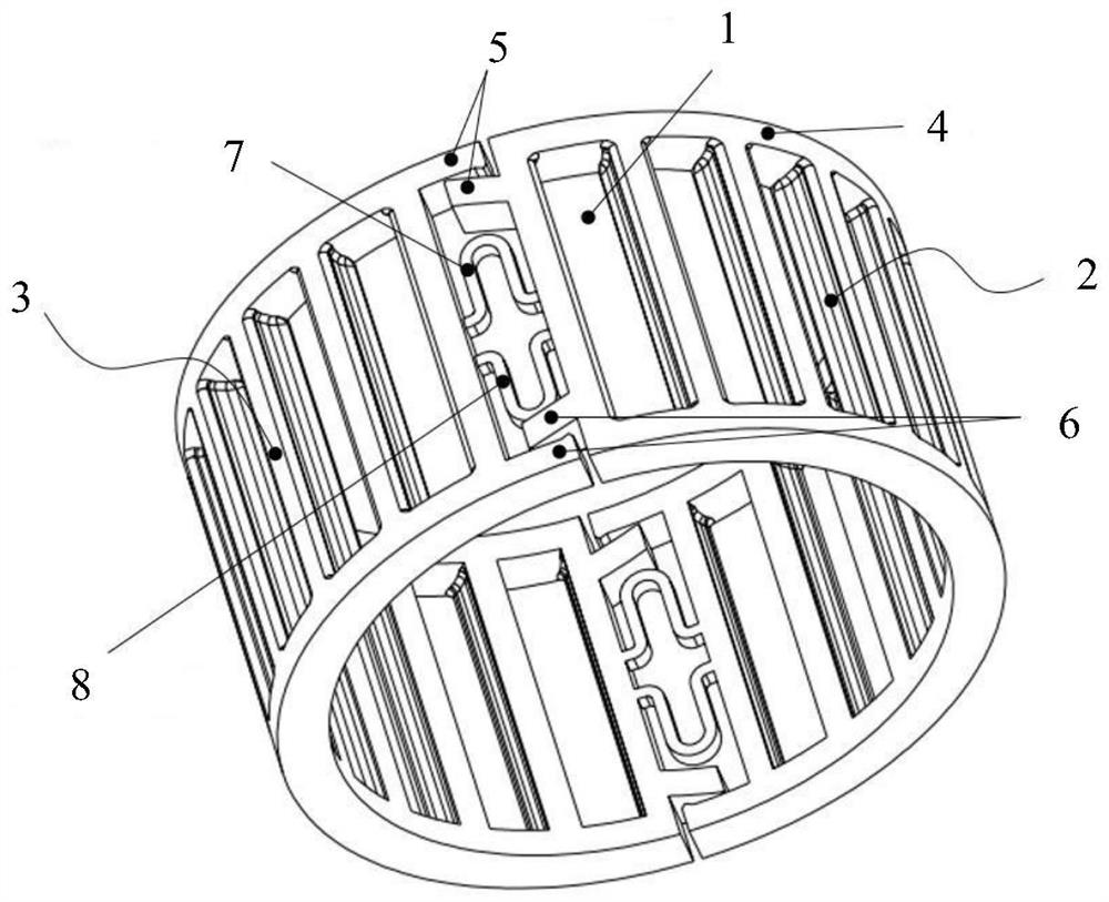
[0026] figure 1 A perspective view of a cage according to a preferred embodiment is shown. In this embodiment, the cage is configured as a nylon cage for needle bearings. The cage is produced in one piece by a molding process.

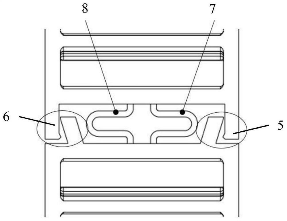
[0027] Such as figure 1 As shown, the cage comprises two cage sections, namely a first cage section 2 and a second cage section 3 . Each cage segment has a row of cage pockets 1 . The two cage sections 2 , 3 extend in the circumferential direction and are here both semi-circular in shape. The two cage sections 2 , 3 are connected to each other by two connections that are elastic in the circumferential direction to form an annular cage. The two connecting parts respectively include a pair of U-shaped springs 7, 8, and the opening directions of each pair of U-shaped springs 7, 8 face each other, and the symmetrical layout of the U-shaped springs 7, 8 can make the cage bear force on both sides in the axial direction balanced. As a result, the tange...


PUM


Abstract

The invention relates to a cage for a rolling bearing and the rolling bearing. The cage comprises at least two cage sections (2, 3), wherein each cage section (2, 3) is provided with at least one row of cage pockets (1); and the cage sections (2, 3) extend in the circumferential direction and are connected to one another by means of elastic connecting parts (7, 8) in the circumferential direction so as to form an annular cage. The rolling bearing comprises the cage.

Description

technical field [0001] The invention relates to cages for rolling bearings. The invention also relates to a rolling bearing comprising such a cage. Background technique [0002] In high-speed operating conditions, matching high-speed bearings are usually required. For example, needle roller bearings can withstand large centrifugal forces and acceleration forces, so they can be used in high-speed operating conditions. Needle roller bearings are usually composed of a radial cage and a plurality of needle rollers located in the radial cage, that is, a needle roller and cage assembly. [0003] The radial cage for needle roller bearings consists of two coaxially arranged side rings and a number of axial beams connecting the two side rings, forming pockets for accommodating needle rollers between the axial beams . For example, Chinese patent documents CN106246728A and CN209354531U all disclose such cages for needle roller bearings. [0004] The function of the cage is to even...

Claims


Application Information

Patent Timeline
Patent Type & Authority Applications(China)
IPC IPC(8): F16C33/46F16C33/48F16C27/04F16C27/06
CPCF16C27/04F16C27/066F16C33/4623F16C33/4635F16C33/4641F16C33/4652F16C33/48F16C2300/22
Inventor 雷飞
Owner SCHAEFFLER TECH AG & CO KG
Why Eureka
Try Eureka