Electromechanical equipment mounting protection device with damping function

A technology of electromechanical equipment and protective devices, applied in the direction of mechanical equipment, springs/shock absorbers, supporting machines, etc., can solve problems such as damage to connecting plates, poor heat dissipation, easy breakage, etc., to prolong service life, reduce damage probability, Counteract the effect of vibration force

Active Publication Date: 2021-07-13
弘毅(温州)建筑工程有限公司
View PDF20 Cites 0 Cited by
  • Summary
  • Abstract
  • Description
  • Claims
  • Application Information

AI Technical Summary

Problems solved by technology

[0004] The above technical solution can effectively dampen the shock and buffer the electromechanical equipment, but the use of sponge pads to contact the electromechanical equipment will cause a very poor local heat dissipation effect. The sponge has the function of absorbing heat, but it absorbs to a certain extent, causing the contact surface temperature to be high. It is not conducive to the heat dissipation of mechanical and electrical equipment;
[0005] In addition, in this technical solution, the threaded rod is used to drive the extruded plate to contact the electromechanical equipment, so as to limit the side of the electromechanical equipment. From the invention figure 1 As shown, when the electromechanical equipment vibrates, the shock-absorbing effect of the sponge pad is limited, and part of the resonance will be transmitted to the connecting plate. At this time, if the connecting plate is long (wide) and covers a large area of ​​the electromechanical equipment, it will inevitably cause difficulty in heat dissipation of the electromechanical equipment; If the connecting plate is relatively short (narrow), due to the right-angle fit between the connecting plate and the supporting plate, the resonance force will cause damage to the lower half of the connecting plate, that is, the connection between the lower half of the connecting plate and the supporting plate is easily broken. Indirectly cause the collapse of the side limit structure of electromechanical equipment

Method used


Image

  • Electromechanical equipment mounting protection device with damping function
  • Electromechanical equipment mounting protection device with damping function
  • Electromechanical equipment mounting protection device with damping function

Examples


Embodiment Construction

[0037] The technical solutions of the present invention will be further described below in conjunction with the accompanying drawings and through specific implementation methods.

[0038] Wherein, the accompanying drawings are only for illustrative purposes, showing only schematic diagrams, rather than physical drawings, and should not be construed as limitations on this patent; in order to better illustrate the embodiments of the present invention, some parts of the accompanying drawings will be omitted, Enlargement or reduction does not represent the size of the actual product; for those skilled in the art, it is understandable that certain known structures and their descriptions in the drawings may be omitted.

[0039] In the drawings of the embodiments of the present invention, the same or similar symbols correspond to the same or similar components; , "inner", "outer" and other indicated orientations or positional relationships are based on the orientations or positional ...


PUM


Abstract

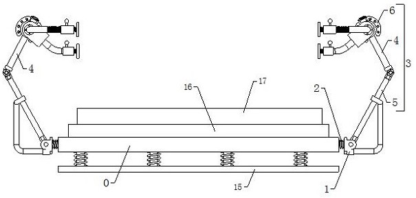
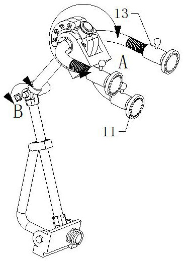
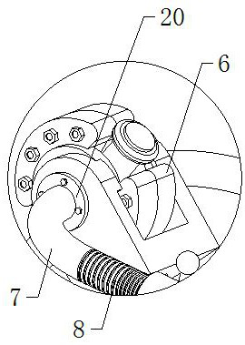
The invention relates to the technical field of electromechanical equipment, in particular to an electromechanical equipment mounting protection device with a damping function. The device comprises a mounting base, a connecting base and a damping framework arranged at the side part of the mounting base. The damping framework comprises an upper shock absorption pipe, a lower shock absorption pipe, a shock absorption guide head and a clamping arm, and a shock absorption cavity is formed in the shock absorption guide head. The distance of the position, close to the top area and the bottom area of the shock absorption guide head, of the shock absorption cavity is larger than the distance of the middle area of the shock absorption cavity, one end of the upper shock absorption pipe penetrates through the shock absorption cavity, the outer surface of the upper shock absorption pipe is in sliding fit with the wall face of the shock absorption cavity, and the other end of the upper shock absorption pipe is in coupling fit with one end of the lower shock absorption pipe through a first torsional spring. The other end of the lower shock absorption pipe is mounted on the connecting base, the connecting base is in coupling fit with the side portion of the mounting base, one end of the clamping arm is connected with the outer surface of the shock absorption guide head, and the other end of the clamping arm is a clamping end. The clamping end extends towards the other side of the mounting base and is provided with a clamping head capable of sliding horizontally. Heat dissipation can be better facilitated while stable limiting work is done.

Description

technical field [0001] The invention relates to the technical field of electromechanical equipment, in particular to an installation protection device for electromechanical equipment with a shock absorbing function. Background technique [0002] The shock absorption effect of the existing installation and protection devices for electromechanical equipment is not good, and it is easy to cause hard collision or vibration between the electromechanical equipment and the ground or the placement platform, which not only generates a lot of noise, but also greatly affects the electromechanical equipment. The use performance and service life, the use effect is not very good. [0003] According to the above problems, after retrieval of Chinese Patent No.: CN201810383392.2, a kind of protection device for electromechanical equipment with shock absorption function, including a base, the upper end of the base is provided with a storage tank, and the inner bottom of the storage tank is fi...

Claims


Application Information

Patent Timeline
Patent Type & Authority Applications(China)
IPC IPC(8): F16F15/02F16F15/067F16M11/04H05K7/20
CPCF16F15/02F16F15/067F16M11/04H05K7/20
Inventor 蔡泰瑞朱小燕王勇
Owner 弘毅(温州)建筑工程有限公司
Why Eureka
Try Eureka