Cavitation venturi tube

A Venturi tube and cavitation technology, applied in the field of aerodynamics, can solve the problems of large fluid pressure loss and easy jamming of the valve core in the throat of the Venturi tube shell, so as to reduce pressure loss and reduce jamming in the throat The effect of not being able to move the spool and reducing the outlet angle

Active Publication Date: 2021-07-13
BEIHANG UNIV
View PDF16 Cites 4 Cited by
  • Summary
  • Abstract
  • Description
  • Claims
  • Application Information

AI Technical Summary

Problems solved by technology

[0007] The purpose of the present invention is to provide a cavitation venturi tube to solve the problems in the prior art that the fluid pressure loss in the cavitation venturi tube is relatively large and the valve core is easily stuck in the throat of the venturi tube shell. Problem; Many technical effects that the preferred technical solution in the many technical solutions provided by the present invention can produce are set forth in detail below

Method used


Image

  • Cavitation venturi tube
  • Cavitation venturi tube
  • Cavitation venturi tube

Examples


Embodiment 1

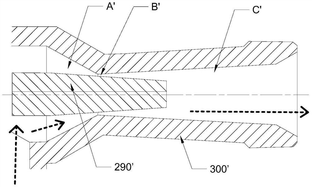
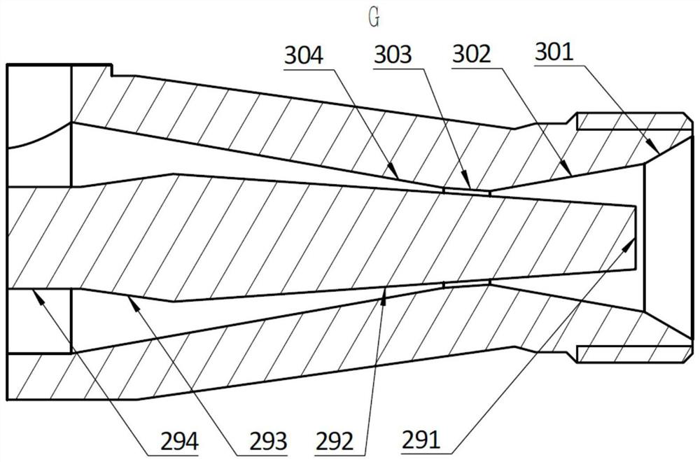
[0051] For the above problems, see figure 2 image 3 and Figure 4 , Figure 8 As shown, this embodiment provides a cavitation venturi, including a valve core 290 and a venturi housing 300, wherein: the flow path in the venturi housing 300 includes constriction sections that are sequentially connected along the fluid flow direction A. Throat B and expansion section C, the spool 290 is movable to adjust the flow of fluid in cooperation with the throat B; the spool 290 has a tapered part, which extends from the expansion section C through the throat to contraction segment A, and the radial section of the tapered portion tends to shrink along the direction from the expansion section C to the contraction section A; preferably, the radial section of the tapered portion gradually decreases along the direction from the expansion section C to the contraction section A.

[0052] Wherein, "constriction section" refers to the radial cross-sectional area of ​​the inner surface of the ...

specific Embodiment approach

[0056] In the present embodiment, the concrete structure of spool 290 is: see Figure 2-Figure 4 shown, see image 3 , the outer wall surface of the spool 290 includes a needle cone surface 292, a needle cone shrinkage surface 293 and a cylindrical surface 294 connected successively along its axial direction, wherein: the needle cone surface 292 is used as the outer wall surface of the tapered part to connect with the throat Form the minimum flow section of the flow path; the part where the cylindrical surface 294 is located is connected with a drive mechanism for driving the valve core 290 to move, and the diameter of the needle cone shrinkage surface 293 is in a decreasing trend along the direction from the needle cone surface 292 to the cylindrical surface 294, so as to Reduce the radial section of the cylindrical surface 294; preferably, the diameter of the needle cone shrinkage surface 293 gradually decreases along the direction of the needle cone surface 292 to the cylin...

Embodiment 2

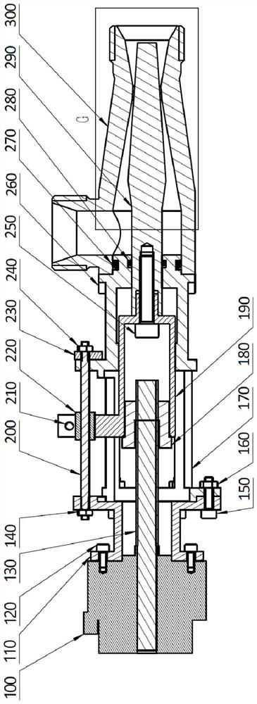
[0082] This embodiment is an improvement on the basis of the first embodiment above, and this embodiment provides a specific implementation of the drive mechanism, see figure 2 , Figure 4 , Figure 5 , Figure 6 As shown, the cavitation venturi also includes a driving mechanism, and the driving mechanism includes a driving device, a lead screw 130, a lead screw nut 180 and a driving block 190, wherein: the output shaft of the driving device is connected with the lead screw 130, and the lead screw 130 is connected with the lead screw 130. The lead screw nut 180 is threaded, one end of the drive block 190 is fixedly connected to the lead screw nut 180, and the other end is fixedly connected to the valve core 290. The structure drives the driving block 190 and the valve core 290 to reciprocate and linearly move along the axial direction.

[0083] Preferably, the driving device in this embodiment is an ultrasonic motor 100, the output shaft of the ultrasonic motor 100 is a ho...


PUM


Abstract

The invention provides a cavitation venturi tube, relates to the technical field of aviation power, and solves the technical problems that the pressure loss of fluid in the cavitation venturi tube is relatively large, and a valve core is easily stuck at the throat part of a venturi tube shell. The cavitation venturi tube comprises a valve element and a venturi tube shell, a flow channel in the venturi tube shell comprises a contraction section, a throat part and an expansion section which are sequentially communicated in the flowing direction of fluid, and the valve element is movably arranged to be matched with the throat part to adjust the flow of the fluid; the valve element is provided with a cone-shaped part, the cone-shaped part extends into the contraction section from the expansion section through the throat part, and the radial section of the cone-shaped part tends to be shrunk in the direction from the expansion section to the contraction section. According to the cavitation venturi tube, the conical part of the valve element extends into the contraction section from the expansion section through the throat part, so that the outlet angle of the expansion section is reduced, the pressure recovery characteristic of the adjustable venturi tube is improved, and the pressure loss is reduced. When the opening degree of the valve element is 0, the situation that the valve element is stuck in the throat part and cannot be moved can be reduced, and stable work of the valve element is guaranteed.

Description

technical field [0001] The invention relates to the technical field of aerodynamics, in particular to a cavitation venturi tube. Background technique [0002] The adjustable cavitation venturi tube is an important flow regulating element, which has superior regulating performance and is widely used in variable thrust liquid rocket engines. It can precisely control the component ratio of propellants and improve the thrust accuracy of variable thrust rocket engines. . [0003] The existing adjustable cavitation venturi mainly includes a venturi shell and a valve core, see figure 1 as shown, figure 1 It is a schematic diagram of the sectional structure of the cooperation between the valve core and the Venturi tube shell in the prior art. The direction of the arrow in the figure indicates the flow direction of the fluid; the end of the valve core extending into the Venturi tube shell is a tapered structure. There is a flow channel in the venturi housing to allow fluid to pas...

Claims


Application Information

Patent Timeline
IPC IPC(8): G05D7/00
CPCG05D7/00
Inventor 张源俊谭广田辉蔡国飙卢裕东陈瑞凯
Owner BEIHANG UNIV
Why Eureka
Try Eureka