Cleaning disc structure of single wafer cleaning device and single wafer cleaning device
A technology for cleaning devices and disks, which is applied in the manufacture of electrical components, circuits, semiconductors/solid-state devices, etc., to achieve the effect of preventing interference
- Summary
- Abstract
- Description
- Claims
- Application Information
AI Technical Summary
Problems solved by technology
Method used
Image
Examples
Embodiment 1
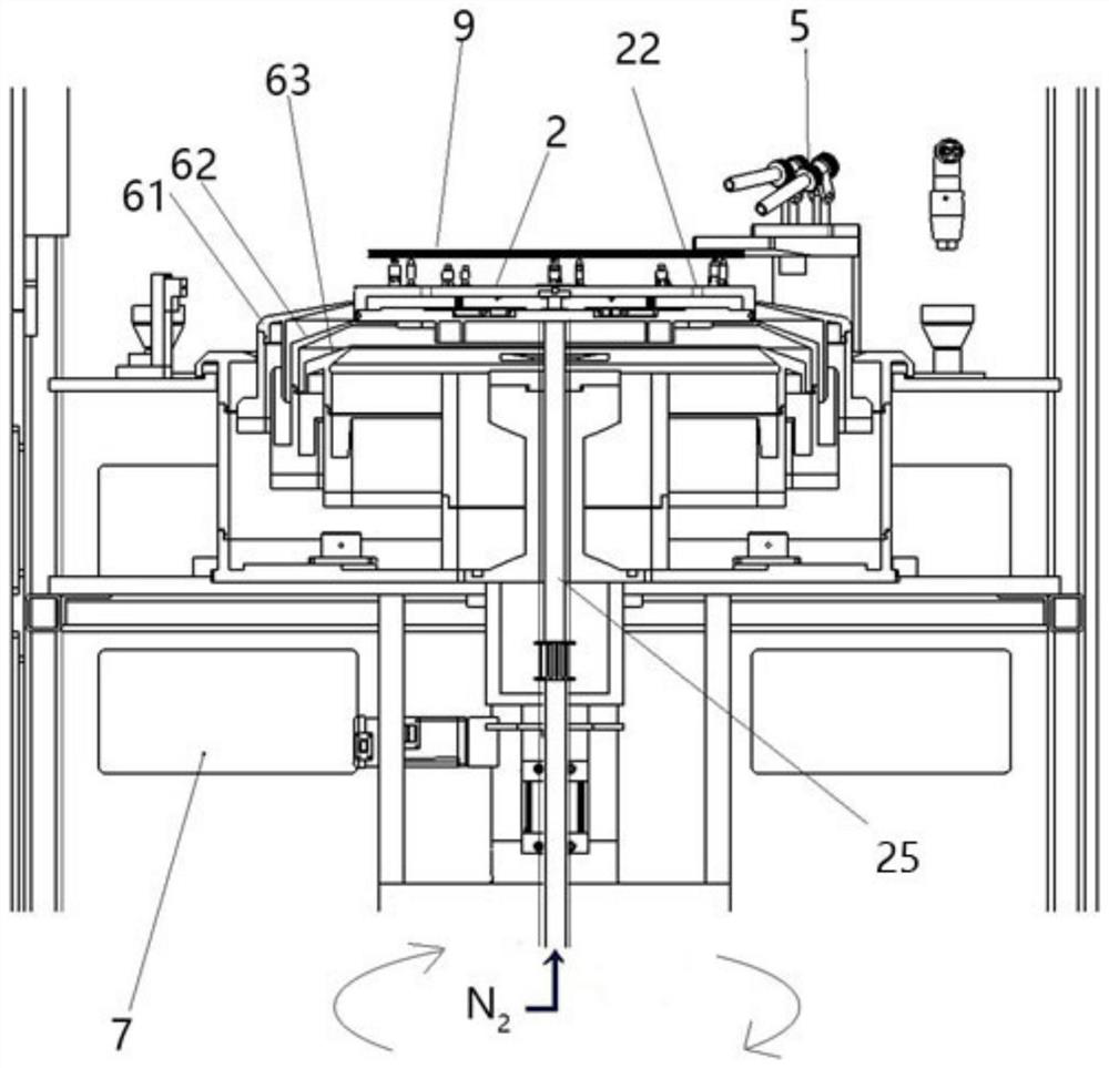
[0057] This embodiment provides a single wafer cleaning device cleaning plate structure, such as figure 2 shown, including:
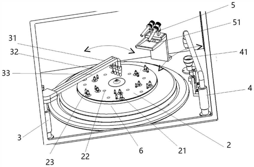
[0058] The support plate 2 can rotate and is used to support and fix the wafer. The bottom of the support plate 2 is connected to the rotating shaft 25, and the rotating shaft 25 is driven by the motor 7 to rotate, thereby causing the support plate 2 to rotate. There is a space in the middle of the support plate 2. cavity 24, the middle of the rotating shaft 25 is a passage, and the passage can pass through the heated nitrogen gas. There are a number of wafer support columns 21 on the disk surface of the support disk 2. There are also passages on the disk surface of the support disk 2. Hole 22, the heated nitrogen gas is ejected from the passage in the middle of the rotating shaft 25 through the cavity 24 from the through hole 22 to heat the wafer and form an air flow at the bottom of the wafer to prevent the cleaning liquid from flowing into the botto...
Embodiment 2
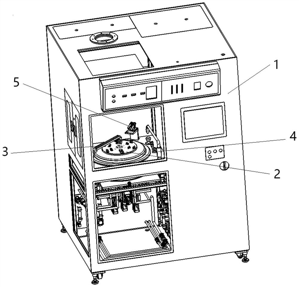
[0071] This embodiment provides a single wafer cleaning device, such as figure 1 shown, including:
[0072] Shell 1 and the structure of the cleaning disc of the single wafer cleaning device inside the shell 1;
[0073] The interior of the housing 1 is divided into several areas by partitions, wherein the horizontal partition divides the interior of the housing 1 into upper and lower parts, and the vertical partition divides the interior of the housing 1 into left and right parts, forming four parts in total. One of the areas is a cleaning area, which is used to set the following components; the housing 1 is also provided with a door for inserting or taking out wafers. Of course, the casing 1 is also provided with an exhaust device to extract some gases inside the casing 1, such as some toxic and harmful gases that are easily volatilized in the cleaning liquid. These toxic and harmful gases cannot be discharged at will and need to be treated. It is relatively common in this ...
Embodiment 3
[0076] This embodiment provides a method for cleaning a single wafer, using the device for cleaning a single wafer in Embodiment 2, comprising the following steps:
[0077] S1: Place the wafer on the support plate 2 with the cleaning surface facing up, make the support plate 2 drive the wafer to rotate, pass the heated nitrogen gas into the cavity 24 of the support plate 2 from the channel in the middle of the rotating shaft 25 and Eject from the through hole 22 on the top of the support plate 2 to heat the wafer and heat the wafer;
[0078] S2: Swing a number of cleaning liquid spray pipes 3 aligned above the center of the wafer, spray the cleaning liquid onto the wafer through the cleaning liquid spray pipes 3, and make the cleaning liquid spray pipes 3 align with the wafer Swing from above the center of the circle to above the edge of the aligned wafer, so that the cleaning liquid reaches the entire surface of the wafer;
[0079] S3: After cleaning for a period of time, st...
PUM
 Abstract
Description
Claims
Application Information
 - R&D Engineer
- R&D Manager
- IP Professional
- Industry Leading Data Capabilities
- Powerful AI technology
- Patent DNA Extraction
Browse by: Latest US Patents, China's latest patents, Technical Efficacy Thesaurus, Application Domain, Technology Topic, Popular Technical Reports.
© 2024 PatSnap. All rights reserved.Legal|Privacy policy|Modern Slavery Act Transparency Statement|Sitemap|About US| Contact US: help@patsnap.com


