

Cap screwing mechanism and control method thereof
A control method and capping technology, which is applied in packaging and other directions, can solve the problems of soft bag packaging container capping and automatic capping equipment being unsuitable, and achieve the effects of compact structure, stable operation, and simplified control process
- Summary
- Abstract
- Description
- Claims
- Application Information
AI Technical Summary
Problems solved by technology
Method used
Image

Examples
Embodiment Construction
[0034] The technical solutions of the present invention will be clearly and completely described below in conjunction with the embodiments of the present invention and the accompanying drawings. Apparently, the described embodiments do not limit the present invention.
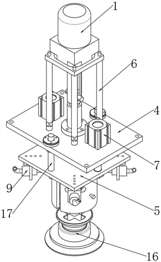
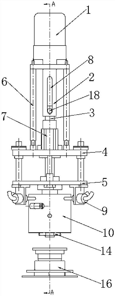
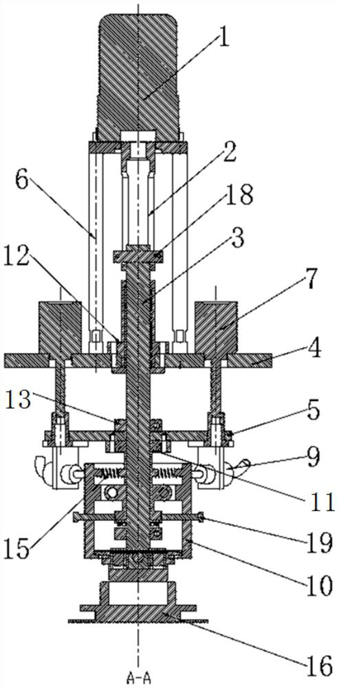
[0035] A cap screwing mechanism, comprising a clamp 10, a guide rod 17, a first platform 4, a second platform 5, a rotating motor 1 connected in sequence, a connecting rod 2 and a rotating elevating rod 3. The rotary motor 1 is fixed to the first platform 4 through a support rod 6 .
[0036] The connecting rod 2 is connected to the output end of the rotating motor 1, and the rotating motor 1 drives the connecting rod 2 to rotate; the connecting rod 2 is provided with a sliding groove along the axial direction, and one end of the rotating lifting rod 3 is connected with the sliding groove 8, The rotating lifting rod 3 can be driven by the connecting rod to rotate synchronously, and can also move along the slidin...
PUM
 Abstract
Description
Claims
Application Information