Grille cleaner

A decontamination machine and grille technology, applied in water/sewage treatment, water/sludge/sewage treatment, special treatment targets, etc., can solve problems such as poor cleaning effect and complex structure

Pending Publication Date: 2021-07-16
合肥市贵谦信息科技有限公司
View PDF5 Cites 2 Cited by
  • Summary
  • Abstract
  • Description
  • Claims
  • Application Information

AI Technical Summary

Problems solved by technology

[0005] The invention provides a grid decontamination machine, which can solve the problems of complex structure and poor cleaning effect of the grid decontamination machine in the prior art

Method used


Image

  • Grille cleaner
  • Grille cleaner
  • Grille cleaner

Examples


Embodiment 1

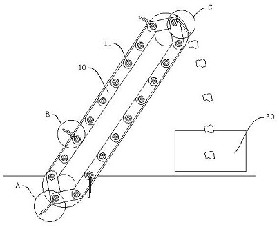
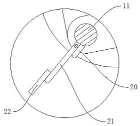
[0032] like Figure 1 to Figure 7 As shown, a grid decontamination machine provided by the embodiment of the present invention includes a decontamination machine body, the decontamination machine body includes a frame, a motor reducer, a chain, etc., and the decontamination machine body also includes a mounting shaft 11 for Rake tine is installed, this part is identical with the structure in the prior art, no longer repeats. like Figure 2 to Figure 4 As shown, the rake tooth includes a stopper 20 and a fishing tooth 21, the stopper 20 is fixedly arranged on the installation shaft 11, one end of the fishing tooth 21 is hinged to the installation shaft 11, and the fishing tooth 21 is located at the movement direction of the stopper 20 along the installation shaft 11 The rear side of the fishing tooth 21 can be turned over a certain angle towards the direction away from the stopper 20 .

[0033] When the decontamination machine is working, the motor reducer drives the chain to...

Embodiment 2

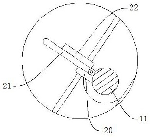
[0035] On the basis of Example 1, as Figure 5 to Figure 7 As shown, the present embodiment also includes an extended tooth 22, and a storage chute is provided on the fishing tooth 21, and a slider 221 is arranged on the elongated tooth 22, and the slider 221 is slidably arranged in the storage chute, and the slider 221 can slide along the Sliding in a direction away from or close to the installation shaft 11 , the elongated teeth 22 and the stopper 20 are located on both sides of the fishing teeth 21 .

[0036] Specifically, the storage chute has a T-shaped structure, and the slider 221 is adapted to the shape of the storage chute, such as Figure 7 As shown, a blanking hole 211 is opened through the receiving chute, and the elongated teeth 22 are shorter than the fishing teeth 21 . like Figure 2 to Figure 4 As shown, when the installation shaft 11 turns to the lower end, the extended teeth 22 slide down under the action of gravity to form a lengthened effect, and more and...

Embodiment 3

[0038] On the basis of Embodiment 1 or 2, because the garbage has a large amount of water after being salvaged from the water surface, it is all relatively troublesome in transportation and post-processing, and needs to be transferred to a dehydration device for dehydration treatment. more, it is easy to cause secondary pollution and increase the difficulty of transportation. Therefore, this embodiment also includes a dehydration device, which includes a dehydration tank 30, a driving device and a pressure device;

[0039] like Figure 8 As shown, the dehydration tank 30 includes a blanking channel 31 and a compression chamber 32, the blanking channel 31 is connected to the compression chamber 32, and the lower end of the blanking channel 31 is inclined towards the compression chamber 32, so that the garbage falls into the container under the action of gravity. Inside the compression chamber 32;

[0040] The pressure device includes a reciprocating screw 58 and a first pressi...


PUM


Abstract

The invention discloses a grille cleaner, belonging to the field of environment-friendly machinery. The grille cleaner comprises a cleaner body, wherein the cleaner body comprises a mounting shaft used for mounting rake teeth, the rake teeth comprise check blocks and fishing teeth, the check blocks are fixedly arranged on the mounting shaft, one ends of the fishing teeth are hinged to the mounting shaft, and the fishing teeth are located on the rear side of the check blocks in the moving direction of the mounting shaft. According to the invention, garbage can be prevented from being blocked by the rake teeth at the lower part when falling, so the falling of the garbage is not influenced; and viscous garbage attached to the fishing teeth can fall off easily, and the fishing teeth are staggered, so the garbage between the adjacent fishing teeth is balanced in destructive power under the action of dislocation formed between the fishing teeth and the garbage can fall off smoothly.

Description

[0001] This application is a divisional application, the original patent number is: 202010795029.9, the application date is August 10, 2020, and the name of the invention is: a pre-dehydration grill decontamination machine. technical field [0002] The invention relates to the field of environmental protection machinery, in particular to a grid decontamination machine. Background technique [0003] The grid decontamination machine is a kind of equipment that uses a mechanical method to remove the grid slag trapped by the grid out of the water. The rotary grill decontamination machine is assembled into a group of rotary grill chains by rake teeth. Driven by the motor reducer, the rake tooth chain rotates against the direction of the water flow, and the garbage is driven above the water surface during the rotation of the rake tooth chain. During the continuous movement, the garbage loses its support after moving to the highest point. Fall under the action of gravity. [00...

Claims


Application Information

Patent Timeline
Patent Type & Authority Applications(China)
IPC IPC(8): C02F1/00
CPCC02F1/00C02F2303/14
Inventor 胡光肖旭时志敏
Owner 合肥市贵谦信息科技有限公司
Why Eureka
Try Eureka