Wet-type deslagging device of biomass gasifier

A gasifier, biomass technology, applied in the manufacture of combustible gas, petroleum industry, etc., to achieve the effect of improving the service life, increasing the contact time, and increasing the weight of ash and slag

Pending Publication Date: 2022-07-15
陈超
0 Cites 0 Cited by

AI-Extracted Technical Summary

Problems solved by technology

[0005] In view of the shortcomings of the existing wet slagging device proposed in the background technology during use, the present invention provides a wet slagging device for a biomass gasification furnace, which can effectively cool...

Abstract

The invention relates to the technical field of biomass energy, and discloses a wet-type slag discharging device of a biomass gasifier, the wet-type slag discharging device comprises a furnace body, the interior of the furnace body is divided into five areas from top to bottom, and the five areas specifically are a drying area, a cracking area, an oxidation area, a reduction area and an ash discharging hopper; one side of the furnace body positioned in the oxidation area is fixedly sleeved with an air inlet piece, the other side of the furnace body positioned in the reduction area is fixedly sleeved with an air outlet piece, the outer wall of the furnace body positioned below the ash discharge hopper is fixedly sleeved with a water tank, and the water tank is filled with liquid water. The fixing columns are arranged in the water tank, the blocking plate and components of the blocking plate can move up and down in the water tank through the side grooves in the outer sides of the fixing columns, ash falls into the top end of the blocking plate before falling into water through blocking of the blocking plate, heat of the ash is transmitted into the water storage part through the conduction part, the initial temperature of the ash is effectively reduced, and the ash can be prevented from falling into the water storage part. And the water impact phenomenon is reduced.

Application Domain

Gasification processes detailsCombustible gas production

Technology Topic

SlagLiquid water +8

Image

  • Wet-type deslagging device of biomass gasifier
  • Wet-type deslagging device of biomass gasifier
  • Wet-type deslagging device of biomass gasifier

Examples

  • Experimental program(1)

Example Embodiment

[0029] The technical solutions in the embodiments of the present invention will be clearly and completely described below with reference to the accompanying drawings in the embodiments of the present invention. Obviously, the described embodiments are only a part of the embodiments of the present invention, but not all of the embodiments. Based on the embodiments of the present invention, all other embodiments obtained by those of ordinary skill in the art without creative efforts shall fall within the protection scope of the present invention.
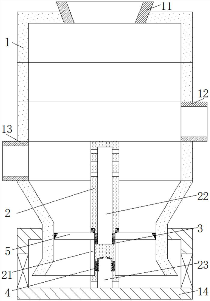
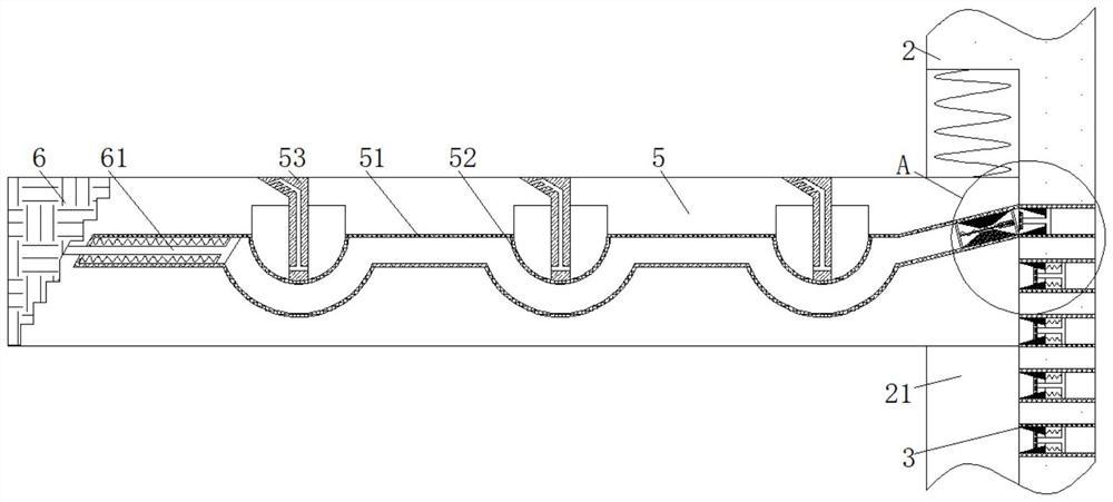
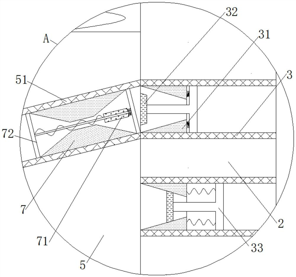
[0030] see Figure 1-Figure 3 , Figure 8, a wet slagging device for a biomass gasifier, comprising a furnace body 1, the interior of the furnace body 1 is divided into five areas from top to bottom, and specifically a drying area, a cracking area, an oxidation area, a reduction area and a discharge area. In the ash hopper, the top of the furnace body 1 is fixedly sleeved with the feeding part 11, the furnace body 1 in the oxidation zone is fixedly sleeved with the gas inlet part 12 on one side, and the gas outlet part 13 is fixed and sleeved on the other side of the furnace body 1 in the reduction zone. The outer wall of the furnace body 1 located below the ash hopper is fixedly sleeved with a water tank 14, and the water tank 14 is filled with liquid water. 1. The outer side is inclined, the middle of the bottom end of the water tank 14 is fixedly connected to the fixed column 2, and the height of the fixed column 2 is from the inner bottom end of the water tank 14 to the top of the reduction area, which can discharge the water vapor generated in the blocking plate 5 to the reduction area. In order to provide raw materials for the reduction reaction, the outer wall of the fixed column 2 located inside the water tank 14 is provided with a side groove 21, and the height range of the side groove 21 is in the middle and lower section of the ash hopper, so that when the blocking plate 5 moves downward, the pushing plate 6 can be moved. According to the cross-sectional shape of the furnace body 1, it moves outward, so as to effectively push the ash floating on the water surface outward, so that there is a clean water area on the water surface near the outer ring of the blocking plate 5, so that the ash and slag at the top of the blocking plate 5 fall down, An upper cavity 22 is opened above the interior of the fixing column 2. The wall surface of the fixing column 2 located in the overlapping part of the side groove 21 and the upper cavity 22 is fixedly sleeved with the intake valve. The blocking block 32, the upper blocking rod 33 and the upper spring are formed. The fixing column 2 is provided with a hole, and the fixing column 2 is fixedly sleeved with the gas valve body 3 through the hole. When the blocking plate 5 corresponds to the gas valve body 3, the water vapor generated in the water storage member in the blocking plate 5 is discharged into the reduction zone through the gas valve body 3, the upper cavity 22, and the gas outlet hole to provide heat and heat for the reduction reaction in the reduction zone. Water vapor, the inner fixed sleeve of the air valve body 3 is connected to the upper limit piece 31, and the inner wall of the upper limit piece 31 is in contact with the upper blocking block 32 with S-shaped magnetism. Small shape, that is, the intake valve is set as a one-way valve. When the position of the resistance member 71 corresponds to the upper blocking block 32, the inlet valve channel is opened so that the water vapor in the water storage member enters the upper cavity 22, and the upper blocking block 32 is opened. One side is fixedly connected with one end of the upper blocking rod 33, the other end of the upper blocking rod 33 penetrates the upper limit piece 31 and is movably sleeved with the inner wall of the gas valve body 3, the upper limit piece 31 and the upper blocking rod 33 are connected. The space is fixed by the upper spring, and the fixed column 2 in the reduction area is provided with an air outlet.
[0031] see figure 1 , Figure 4-Figure 5 , Figure 7 , Further, a lower cavity 23 is opened under the interior of the fixed column 2, and the water outlet valve is fixedly sleeved on the wall surface of the fixed column 2 at the overlapping part of the side groove 21 and the lower cavity 23. The water outlet valve is composed of the water valve body 4 and the lower blocking rod 41 , The lower blocking block 42 and the lower spring are formed, the wall surface of the fixing column 2 is provided with a hole, and the fixing column 2 is fixedly sleeved with the water valve body 4 through the hole. When the blocking plate 5 corresponds to the water valve body 4, the water vapor in the water storage member is discharged from the water valve body 4 into the lower chamber 23, and impacts the liquid water in the lower chamber 23, so that the water mist is fine and dense, so that the ash and slag can be fully removed. Wetting and cooling, at the same time, the liquid water in the lower chamber 23 enters the water storage member, so that the water storage member is supplemented with water and cooled down, so as to provide a new water source for the subsequent blocking plate 5 to rise again and convert the water into water vapor again. The water valve body 4 is as follows: The oblique downward setting from the inside of the fixed column 2 to the outside can make the water discharged from the water valve body 4 obliquely impact the ash at the top of the blocking plate 5, so that the ash can be smoothly discharged into the water in the water tank 14, and at the same time close to the blocking plate 5. The inclination angle of the transverse membrane 51 of the inner ring is the same as the inclination angle of the water valve body 4, so that the water in the lower cavity 23 can be smoothly filled into the water storage member, and the water in the water storage member can be converted into water vapor to provide raw materials. The top of the fixing column 2 inside the cavity 23 is provided with a lower groove, and the fixing column 2 is movably connected with the top end of the lower blocking rod 41 through the lower groove. The magnetic repulsion force is smaller than the magnetic repulsion force of the resistance member 71 to the lower blocking rod 41 , that is, the water outlet valve is a one-way valve. When the position of the resistance member 71 corresponds to the lower blocking rod 41 , the water outlet valve is opened to promote the exchange of water and water vapor. At the same time, the water with bubbles is discharged to the top of the blocking plate 5, the side of the lower blocking rod 41 corresponding to the position of the water valve body 4 is fixedly connected to the lower blocking block 42, and the water valve body 4 and the lower groove are connected by a lower spring , the fixing column 2 located below the side groove 21 is provided with a water inlet hole.
[0032] see Figure 1-Figure 3 , Figure 5-Figure 8 , Further, the fixed column 2 is movably connected to one end of the blocking plate 5 through the side groove 21, and the top end of the blocking plate 5 and the top end of the side groove 21 are connected by a large spring, and the interior of the blocking plate 5 is provided with irregular grooves, And the blocking plate 5 is fixedly sleeved with the water storage member through the irregular groove, the water storage member is composed of a transverse film 51 and a curved film 52, and the transverse film 51 and the curved film 52 are alternately arranged, and the top of the curved film 52 is movable with the irregular groove. Connection, that is, the curved membrane 52 is arranged in an arc shape, which can effectively store liquid water. The top end of the curved membrane 52 is fixedly connected to one end of the conducting member 53, and the other end of the conducting member 53 penetrates the top of the blocking plate 5. The shape of the conducting member 53 is Inverted L-shaped, and the top end is biased towards the outer ring of the blocking plate 5, the inner part of the conducting member 53 is provided with a blowing hole, and the blowing direction of the blowing hole is obliquely downward to the outer ring of the blocking plate 5. 5. The ash at the top is blown towards the edge of the blocking plate 5, which not only reduces the temperature of the ash itself, but also helps the ash to fall into the water later. , the other end of the push rod 61 penetrates the blocking plate 5 and is fixedly connected to one side of the push plate 6. The shape of the push plate 6 is a triangle, and the inclined surface of the triangle is serrated, and the inclined surface of the push plate 6 is connected to the outer ring of the blocking plate 5. The snap connection can form a closed whole when the blocking plate 5 and the pushing plate 6 are in contact, so that when the blocking plate 5 and the pushing plate 6 descend together, the water below them is compressed into the lower cavity 23, and the water is released by the water valve body 4 for the subsequent water. The injection provides conditions. There is a connecting net between the two pushing plates 6, so that when the pushing plate 6 moves outward, the connecting net and the pushing plate 6 form a complete area around the blocking plate 5, so as to isolate the floating ash. Outside this area, the transverse membrane 51 and the push rod 61 are connected by a first spring, and the inner wall of the transverse membrane 51 close to the inner circle of the blocking plate 5 is fixed to the sleeve fixing member 7, and the inner cavity of the fixing member 7 is large on both sides and in the middle Small shape, and the middle of the fixing member 7 is adapted to the size of the resistance member 71, that is, the fixing member 7 is set as a two-way valve, which can make the passage of the fixing member 7 open when the resistance member 71 moves to both sides, so that the water vapor can be opened. Out, liquid water enters, the inner walls of the transverse membrane 51 on both sides of the fixing member 7 are fixedly connected to the support rods 72, the two support rods 72 are connected by a cross rod, and the external movable sleeve of the cross rod has an N-type magnetic resistance. The two ends of the blocking member 71 and the support rod 72 are connected by a second spring.
[0033] figure 2 and Figure 5 It is a structural diagram of the blocking plate 5 in different positions of the side groove 21. Specifically, as in figure 2 At this time, the blocking plate 5 corresponds to the valve body 3. Because the pushing plate 6 is in the middle of the ash hopper, the inclined surface of the pushing plate 6 is clamped with the edge of the blocking plate 5, and the blocking member 71 and the upper blocking block 32 are received by two The magnetic attraction between them attracts each other, the corresponding resistance member 71 moves outward, and the upper blocking block 32 moves outward, thereby opening the air inlet valve channel to allow water vapor to enter the upper cavity 22 and be discharged through the air outlet above the fixed column 2. Since the water vapor in the water storage member is discharged in time, the conduction member 53 does not rise much due to the curved film 52. Therefore, it can be inferred that when the blocking plate 5 continues to descend and is located between the air valve body 3 and the water valve body 4, the water The steam cannot be discharged and pushes the conduction member 53 to lift up so that the ash and slag are scattered; Figure 5 At this time, the blocking plate 5 corresponds to the water valve body 4. Because the pushing plate 6 is located below the ash hopper, the pushing plate 6 is moved outward by the air pressure in the transverse film 51, and a ash-free slag is isolated around the blocking plate 5. The floating area, so that the ash at the top of the blocking plate 5 falls, the magnetic repulsion between the blocking member 71 and the lower blocking rod 41 acts to repel each other, and the corresponding blocking member 71 moves inward and the lower blocking rod 41 moves inward, thereby Open the water outlet valve to push the water vapor in the water storage member into the lower chamber 23, and the water in the lower chamber 23 enters the water storage member, so as to provide raw materials for subsequent water evaporation into water vapor, and at the same time, the water in the lower chamber 23 is ejected through the water valve body 4. into the top of the baffle plate 5 to discharge the ash into the water.
[0034] The working principle of the using method of the present invention is as follows:
[0035] Start the biomass gasification furnace, put raw materials into the furnace body 1 through the feeding part 11, and pass air into the furnace body 1 through the air intake part 12, so that the raw materials are gasified through the drying zone, cracking zone, oxidation zone and reduction zone. The biomass gas is then generated and discharged from the gas outlet 13, and the generated ash is discharged into the fixed column 2 through the ash hopper of the furnace body 1. During this process, when there is no ash at the top of the blocking plate 5, it is subjected to a large spring. The pulling force is located above the water surface. As the ash and slag fall, the top of the blocking plate 5 continuously accumulates ash and slag, so that the weight of the blocking plate 5 increases and then descends along the side groove 21, and pushes the liquid water in the fixed column 2 into the downward cavity 23. Move and raise the water surface position in the lower chamber 23 to facilitate the subsequent discharge of water in the lower chamber 23. When the blocking plate 5 is at the height of the valve body 3, the ash on the top of the blocking plate 5 transfers heat to the water storage through the conduction member 53 The liquid water in the component is heated and converted into water vapor, thereby reducing the initial temperature of the ash. The water vapor is discharged into the upper cavity 22 through the gas valve body 3, and then discharged into the reduction zone through the air outlet to provide heat and water vapor for the reduction zone, so that the reduction reaction is sufficient. When it is between the water valve bodies 4, the water vapor in the water storage member cannot be discharged at this time, thus pushing the conducting member 53 to move outward, so that the ash at the top of the blocking plate 5 is in a state of staggered distribution, which further affects the internal flow of the ash and slag. The heat of the slag is dissipated, thereby reducing the temperature of it falling into the water and reducing the occurrence of water impact when the ash falls into the water. When the blocking plate 5 falls to the height of the water valve body 4, the pushing plate 6 is affected by the air pressure in the transverse membrane 51. Then, the connecting net and the pushing plate 6 move the ash in the water outward, so that a clean ash falling area is formed around the blocking plate 5. At this time, the magnetic repulsion between the blocking member 71 and the lower blocking rod 41 acts. The water inlet valve channel is opened, the water vapor in the water storage member moves to the lower chamber 23, and the water in the lower chamber 23 moves to the water storage member, which provides conditions for the blocking plate 5 to continuously reduce the heat of the ash and slag, and at the same time, it is collided by the water vapor. The water also moves to the top of the blocking plate 5 through the water valve body 4, so as to wet the ash at the top of the blocking plate 5, thereby increasing the weight of the ash, and rushing the ash to the edge of the blocking plate 5 until it falls into the In the water, when there is no more ash at the top of the baffle plate 5, the baffle plate 5 is moved back up to its original position by the pulling force of the large spring. In summary, the reciprocating movement of the baffle plate 5 ensures that the ash and slag fall into the water smoothly and improves the slag discharge. efficiency.

PUM

no PUM

Description & Claims & Application Information

We can also present the details of the Description, Claims and Application information to help users get a comprehensive understanding of the technical details of the patent, such as background art, summary of invention, brief description of drawings, description of embodiments, and other original content. On the other hand, users can also determine the specific scope of protection of the technology through the list of claims; as well as understand the changes in the life cycle of the technology with the presentation of the patent timeline. Login to view more.

Similar technology patents

Punching positioning device

InactiveCN103394731AThe punching position is accurateExtended service life
Owner:STATE GRID CORP OF CHINA +1

Quick shredding device for medical abandoned medicine packaging boxes

InactiveCN106179641AProtection of rotating electrical machinesExtended service life
Owner:李汉文

Method for preparing abrasion-resistant super-hydrophobic ceramic coating through thermal spraying technology and product

ActiveCN105316619AExtended service lifegood self-cleaning
Owner:NINGBO INST OF MATERIALS TECH & ENG CHINESE ACADEMY OF SCI
Why Eureka
Try Eureka