
Transmission line structure and manufacturing method thereof, phase shifter and liquid crystal antenna

A technology of transmission line structure and manufacturing method, which is applied in the field of signal transmission, and can solve problems such as large resistance thickness of metal wires, influence on alignment uniformity, and damage to friction cloth

Pending Publication Date: 2021-07-16
CHENGDU TIANMA MICROELECTRONICS
View PDF22 Cites 0 Cited by
  • Summary
  • Abstract
  • Description
  • Claims
  • Application Information

AI Technical Summary

Problems solved by technology

[0003] In the existing transmission line structure, the thickness of the metal wire resistance is relatively large, which causes an increased step difference in the transmission line structure. During the friction alignment process, it is very likely that the friction cloth will be damaged by the edge of the high step difference, which will affect the alignment uniformity. Affect the normal operation of the transmission line

Method used


Image

  • Transmission line structure and manufacturing method thereof, phase shifter and liquid crystal antenna
  • Transmission line structure and manufacturing method thereof, phase shifter and liquid crystal antenna
  • Transmission line structure and manufacturing method thereof, phase shifter and liquid crystal antenna

Examples


Embodiment Construction

[0052] Various exemplary embodiments of the present invention will now be described in detail with reference to the accompanying drawings. It should be noted that the relative arrangements of components and steps, numerical expressions and numerical values ​​set forth in these embodiments do not limit the scope of the present invention unless specifically stated otherwise.

[0053] The following description of at least one exemplary embodiment is merely illustrative in nature and in no way taken as limiting the invention, its application or uses.

[0054] Techniques, methods and devices known to those of ordinary skill in the relevant art may not be discussed in detail, but where appropriate, such techniques, methods and devices should be considered part of the description.

[0055] In all examples shown and discussed herein, any specific values ​​should be construed as exemplary only, and not as limitations. Therefore, other instances of the exemplary embodiment may have dif...


PUM


Abstract

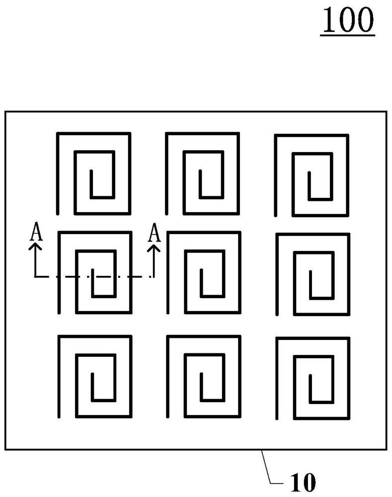
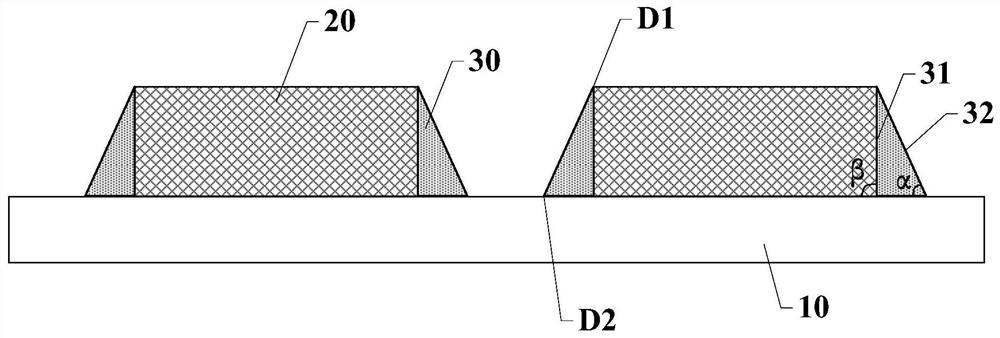
The invention discloses a transmission line structure and a manufacturing method thereof, a phase shifter and a liquid crystal antenna, and relates to the technical field of signal transmission. The transmission line structure comprises a first substrate, a first conductive part and a first auxiliary part; the first auxiliary part is arranged on the side surface of the first conductive part along the direction parallel to the first substrate, the first side surface of the first auxiliary part is contacted with the first conductive part, and the second side surface is positioned on one side of the first side surface away from the first conductive part; the second side surface comprises a first end part and a second end part; the second end part is positioned on one side, far away from the first conductive part, of the first end part; in the direction perpendicular to the first substrate, the distance between the first end and the first substrate is larger than the distance between the second end and the first substrate. The acute angle of the included angle between the extension direction of the second side surface and the extension direction of the plane where the first substrate is located is alpha, the included angle between the bottom surface and the side surface of the first conductive part is beta, and alpha is smaller than beta. Therefore, the in-plane alignment uniformity of the transmission line structure can be improved.

Description

technical field [0001] The invention relates to the technical field of signal transmission, and more specifically, to a transmission line structure and a manufacturing method thereof, a phase shifter and a liquid crystal antenna. Background technique [0002] With the continuous development of communication technology, people's demand for communication with large capacity and high transmission speed is increasing. The transmission line structure is an important part of the communication medium. For example, liquid crystal antennas and other devices contain transmission line structures. Among them, the liquid crystal antenna is a method that uses the dielectric anisotropy of liquid crystals to change the dielectric constant of liquid crystals by controlling the deflection direction of liquid crystals. , so as to change the phase shift size of the phase shifter, thereby adjusting the alignment direction of the phased array antenna. Compared with traditional horn antennas, hel...

Claims


Application Information

Patent Timeline
IPC IPC(8): G02F1/1337G02F1/13H01Q3/30H01P1/18
CPCG02F1/133784G02F1/1313H01Q3/30H01P1/18
Inventor 杨作财段勤肄何宁王东花扈映茹席克瑞贾振宇陈飞
Owner CHENGDU TIANMA MICROELECTRONICS
Learn More