Check patentability & draft patents in minutes with Patsnap Eureka AI!

Over-temperature protection circuit

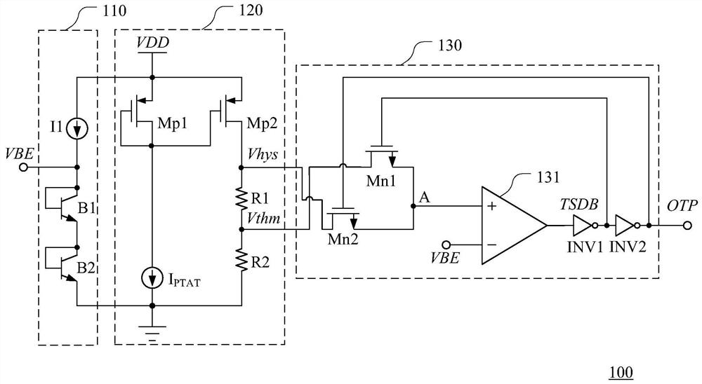
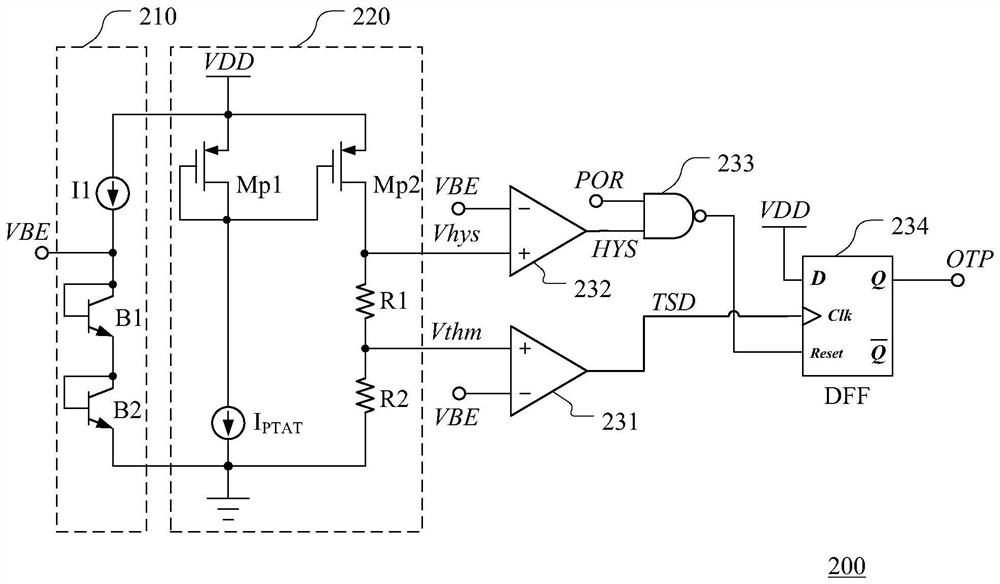
A technology of an over-temperature protection circuit and a voltage generating circuit, which is applied to emergency protection circuit devices, circuit devices, emergency protection devices for automatic disconnection, etc., and can solve the problems that the state of transistor Mn1 and transistor Mn2 cannot be determined, the chip cannot start normally, and the Over-temperature protection false triggering and other problems, to achieve the effect of solving the effect of over-temperature protection false triggering

Pending Publication Date: 2021-07-16
SG MICRO
View PDF0 Cites 3 Cited by
  • Summary
  • Abstract
  • Description
  • Claims
  • Application Information

AI Technical Summary

Problems solved by technology

[0008] The disadvantage of the traditional over-temperature protection circuit is that when the chip is started at a temperature between the return temperature threshold and the over-temperature threshold, since the initial output level of the comparator cannot be determined, the states of the transistor Mn1 and the transistor Mn2 cannot be determined when the chip is started. OK, this brings the possibility of false triggering of over-temperature protection
For example, if the initial output of the comparator 131 is at a high level and remains at a high level state before the circuit is started, the transistor Mn1 is turned off when the chip is started, and the transistor Mn2 is turned on, because the detection voltage VBE is less than the second threshold Voltage Vhys, so comparator 131 outputs a high level, the over-temperature control signal OTP is high-level, and the temperature return control signal TSDB is low-level, the chip directly enters the over-temperature protection, so that the chip cannot start normally

Method used


Image

  • Over-temperature protection circuit
  • Over-temperature protection circuit
  • Over-temperature protection circuit

Examples


Embodiment Construction

[0025] Various embodiments of the invention will be described in more detail below with reference to the accompanying drawings. In the various drawings, the same elements are denoted by the same or similar reference numerals. For the sake of clarity, various parts in the drawings have not been drawn to scale.

[0026] It should be understood that in the following description, a "circuit" refers to a conductive loop formed by at least one element or sub-circuit through electrical or electromagnetic connections. When an element or circuit is said to be "connected to" another element or an element / circuit is said to be "connected between" two nodes, it can be directly coupled or connected to the other element or there can be intervening elements and the connection between elements can be be physical, logical, or a combination thereof. In contrast, when an element is referred to as being "directly coupled to" or "directly connected to" another element, there are no intervening e...


PUM


Abstract

The invention discloses an over-temperature protection circuit, which comprises a detection voltage generation circuit, a threshold voltage generation circuit, a first comparator, a second comparator, a NAND gate and a logic circuit, wherein the first comparator is used for generating a first comparison signal according to a detection voltage and a first threshold voltage; the second comparator is used for generating a second comparison signal according to the detection voltage and a second threshold voltage; the NAND gate is used for generating a reset signal according to the second comparison signal and the power-on reset signal; and the logic circuit is used for carrying out setting operation according to the first comparison signal and carrying out reset operation according to the reset signal so as to generate an over-temperature control signal. When the chip is started at the temperature between the temperature return threshold value and the over-temperature threshold value, the power-on reset signal is in a low level, so that the reset signal is in a high level, the logic circuit executes reset operation according to the reset signal, and the over-temperature control signal is output to be in a low level. Therefore, the problem of over-temperature protection false triggering when the chip is started between the temperature return threshold value and the over-temperature threshold value is solved.

Description

technical field [0001] The present invention relates to the technical field of chip over-temperature protection, and more particularly, relates to an over-temperature protection circuit. Background technique [0002] Over Temperature Protection (OTP) circuits are widely used in power circuits to prevent the circuit from working abnormally or even being burned due to excessive chip temperature. The principle is to use temperature sensitive devices to monitor the chip temperature. When the chip temperature is higher than the over-temperature threshold, a control signal is output to shut down the circuit; when the chip temperature drops to the return temperature threshold, another control signal is output to continue the circuit. Work. [0003] Such as figure 1 A schematic structural diagram of a traditional over-temperature protection circuit is shown. Such as figure 1 As shown, the traditional over-temperature protection circuit 100 includes a detection voltage generation...

Claims


Application Information

Patent Timeline
IPC IPC(8): H02H5/04H02H1/00G01R19/165
CPCH02H5/04H02H1/0007G01R19/16557
Inventor 张利地
Owner SG MICRO
Features
  • R&D
  • Intellectual Property
  • Life Sciences
  • Materials
  • Tech Scout
  • Unparalleled Data Quality
  • Higher Quality Content
  • 60% Fewer Hallucinations
Learn More