
Magnetic steel positioning structure, motor and installation tool of magnetic steel positioning structure

A positioning structure, installation tooling technology, applied in the direction of magnetic circuit shape/style/structure, electromechanical devices, manufacturing motor generators, etc., can solve the problems of increasing the difficulty and cost of back iron processing, to simplify the installation and positioning process, ensure The effect of positioning accuracy, reducing processing difficulty and manufacturing cost

Pending Publication Date: 2021-07-16
SHANGHAI PANGOOD POWER TECH CO LTD
View PDF0 Cites 2 Cited by
  • Summary
  • Abstract
  • Description
  • Claims
  • Application Information

AI Technical Summary

Problems solved by technology

Since the position of the magnetic steel on the back iron needs to be positioned, the general practice in the prior art is to process positioning structures such as positioning bosses on the surface of the back iron. However, the positioning boss structure increases the processing difficulty and cost of the back iron

Method used


Image

  • Magnetic steel positioning structure, motor and installation tool of magnetic steel positioning structure
  • Magnetic steel positioning structure, motor and installation tool of magnetic steel positioning structure
  • Magnetic steel positioning structure, motor and installation tool of magnetic steel positioning structure

Examples


Embodiment Construction

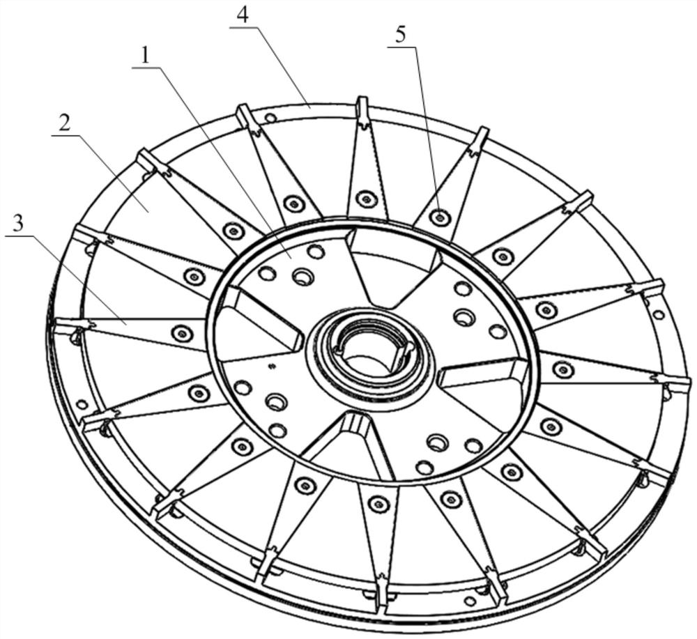
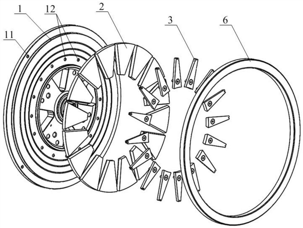
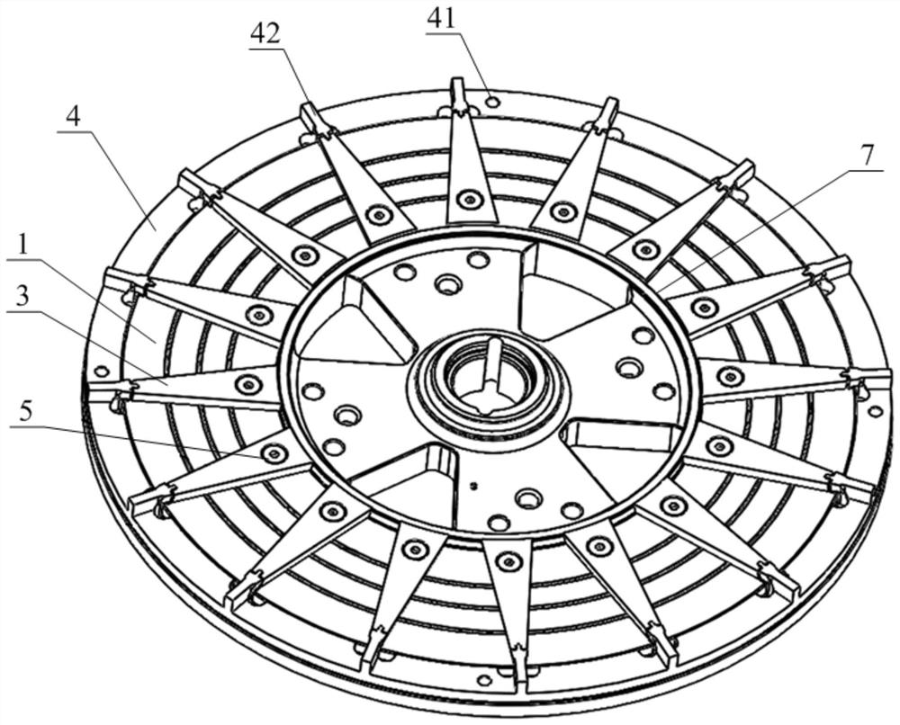
[0034] The solution of the present invention provides a magnetic steel positioning structure, which does not need to process positioning structures such as bosses on the surface of the rotor back iron, simplifies the structure and processing difficulty of the rotor back iron, and can perform axial positioning and positioning of the magnetic steel. Circumferential positioning as well as radial positioning. The following will clearly and completely describe the technical solutions in the embodiments of the present invention with reference to the accompanying drawings in the embodiments of the present invention. Obviously, the described embodiments are only some, not all, embodiments of the present invention. Based on the embodiments of the present invention, all other embodiments obtained by persons of ordinary skill in the art without making creative efforts belong to the protection scope of the present invention.

[0035] Please refer to Figure 1 to Figure 7 , Figure 1 to ...


PUM


Abstract

A magnetic steel positioning structure disclosed by the present invention comprises a rotor back iron, magnetic steel pressing plates and a peripheral positioning ring, the plurality of magnetic steel pressing plates are uniformly distributed and fixed on the surface of the rotor back iron along the circumferential direction, and the rotor back iron is provided with pressing plate fixing holes in one-to-one correspondence with the plurality of magnetic steel pressing plates. Magnetic steel mounting grooves for allowing the magnetic steel to be inserted from outside to inside along the radial direction of the rotor back iron are formed between adjacent magnetic steel pressing plates, axial limiting structures for limiting the axial movement of the magnetic steel relative to the rotor back iron are arranged on the side surfaces, facing the magnetic steel mounting grooves, of the magnetic steel pressing plates, and the peripheral positioning rings are positioned on the peripheries of the magnetic steel pressing plates and the magnetic steel along the radial direction of the rotor back iron. According to the scheme, the magnetic steel can be positioned in the axial direction, the circumferential direction and the radial direction of the rotor back iron, a boss structure on the surface of the rotor back iron is omitted, the magnetic steel pressing plate can be fixed only through the pressing plate fixing holes, and the machining difficulty and cost of the rotor back iron are greatly reduced. The invention further discloses a motor comprising the magnetic steel positioning structure and an installation tool of the magnetic steel positioning structure.

Description

technical field [0001] The invention relates to the technical field of motor structure design, in particular to a magnetic steel positioning structure, a motor and an installation tool for the magnetic steel positioning structure. Background technique [0002] For the rotor disk of a disk motor with a middle stator and rotors on both sides, or a rotor disk of a disk motor with a single stator and a single rotor, in the structure of the rotor disk, the magnetic steel needs to be fixedly installed on the back iron. Since the position of the magnetic steel on the back iron needs to be positioned, the general practice in the prior art is to process positioning structures such as positioning bosses on the surface of the back iron. However, the positioning boss structure increases the processing difficulty and cost of the back iron . [0003] Therefore, how to reduce the processing difficulty and cost of the back iron while realizing the positioning of the magnetic steel is a tec...

Claims


Application Information

Patent Timeline
Patent Type & Authority Applications(China)
IPC IPC(8): H02K1/28H02K1/27H02K15/03
CPCH02K1/2793H02K1/28H02K15/03H02K1/27H02K1/30
Inventor 汤磊张广权李一雄
Owner SHANGHAI PANGOOD POWER TECH CO LTD
Learn More