Check patentability & draft patents in minutes with Patsnap Eureka AI!

Flyback converter control method and device

A flyback converter and control device technology, applied in the direction of output power conversion device, control/regulation system, DC power input conversion to DC power output, etc., can solve the problem of large loss, high cost of flyback converter, and complicated control And other issues

Active Publication Date: 2021-07-16
MORNSUN GUANGZHOU SCI & TECH
View PDF6 Cites 0 Cited by
  • Summary
  • Abstract
  • Description
  • Claims
  • Application Information

AI Technical Summary

Problems solved by technology

[0005] In view of the above-mentioned problems existing in the prior art, the purpose of the present invention is to provide a flyback converter control method and a control device thereof, so as to realize the zero-voltage turn-on (ZVS) of the primary side power switch tube, improve the transmission efficiency of the converter, and solve the problem of The upper tube clamp flyback converter on the primary side has the problems of high cost and complex control. In addition, it can solve the problem of large loss under light load and no-load conditions caused by the turn-on and turn-off of the auxiliary switch tube.

Method used


Image

  • Flyback converter control method and device
  • Flyback converter control method and device
  • Flyback converter control method and device

Examples


Embodiment Construction

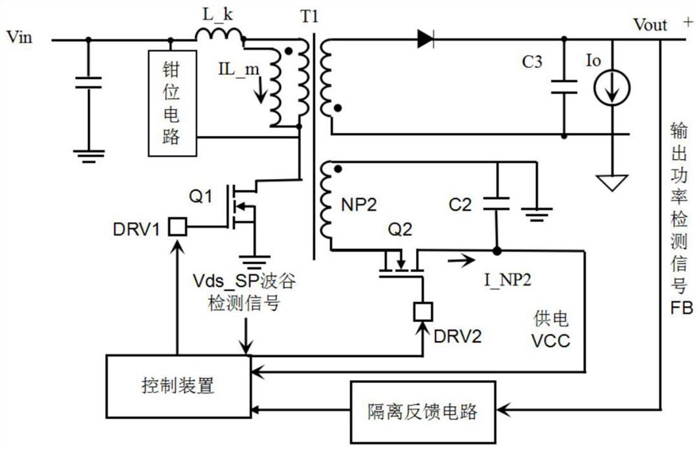
[0024] figure 1 A flyback converter according to an embodiment of the present invention includes a flyback switching power supply circuit, an auxiliary power supply circuit, an isolated feedback circuit and a control device. The auxiliary power supply circuit includes capacitor C2, auxiliary switch tube Q2 and auxiliary winding NP2. The control device has the following signal ports: power supply VCC terminal, DRV1 terminal, DRV2 terminal, detection terminal and feedback signal detection terminal. The output of DRV1 terminal controls the primary side main circuit. The first drive signal of the power switch tube Q1 is output through the DRV2 terminal to control the second drive signal of the auxiliary switch tube Q2, the peak of the drain-source voltage Vds of the primary side power switch tube Q1 is detected through the detection terminal, and the output power is obtained through the feedback signal detection terminal Detection signal FB. The specific connection relationship i...


PUM


Abstract

The invention provides a flyback converter control method and device. A flyback converter comprises a flyback switching power supply circuit, an auxiliary power supply circuit, an isolation feedback circuit and a control device, the control device controls the flyback converter to work in different modes by judging output load power, and when the output power is smaller than a first threshold value, the flyback converter works in a conventional mode; when the output power is larger than or equal to the first threshold value, the working mode is that the auxiliary winding injects energy stored in a capacitor in a reverse excitation mode into a primary winding, negative current generated by the primary winding flows to a power input positive end through a parasitic diode of the primary side power tube, and before the negative current of the primary winding is turned over, the control device controls the primary side power switch tube to be switched on, and zero-voltage switch-on of the primary side power switch tube is achieved. Compared with the prior art, under the condition that zero-voltage conduction of the primary power switch tube and the secondary power switch tube is achieved, loss under light and no-load conditions is reduced, and working efficiency under the light and no-load conditions is guaranteed.

Description

technical field [0001] The invention relates to the field of flyback converters, in particular to the control of the working mode of the flyback converter. Background technique [0002] At present, the quasi-resonant flyback converter (QRFlyback) can realize the zero-voltage turn-on (ZVS) of the primary-side power switch tube at low-voltage input, and can realize the valley-bottom turn-on of the primary-side power switch tube at high-voltage input, which can significantly reduce Small switching loss is currently the most popular circuit topology used in low-power switching power supplies. However, with the development of high frequency, the turn-on loss of the quasi-resonant flyback converter is increasing at high voltage input, which seriously affects the efficiency of the converter in the full input voltage range. In order to solve the problem that the quasi-resonant flyback converter cannot fully realize the zero-voltage turn-on (ZVS) of the primary side power switch tub...

Claims


Application Information

Patent Timeline
IPC IPC(8): H02M3/335H02M1/08
CPCH02M3/33592H02M1/08H02M1/083Y02B70/10
Inventor 邓世源李樟红王海洲
Owner MORNSUN GUANGZHOU SCI & TECH
Features
  • R&D
  • Intellectual Property
  • Life Sciences
  • Materials
  • Tech Scout
  • Unparalleled Data Quality
  • Higher Quality Content
  • 60% Fewer Hallucinations
Learn More