Cable binding frame installation tool

A technology for installing tooling and lashing racks, which is applied to ships and other directions, can solve problems such as slipping and falling, splash damage, etc., and achieve the effect of improved aesthetics, good versatility, and neat installation

Pending Publication Date: 2021-07-20
CHENGXI SHIPYARD
View PDF0 Cites 1 Cited by
  • Summary
  • Abstract
  • Description
  • Claims
  • Application Information

AI Technical Summary

Problems solved by technology

During the construction, there is often an upward welding posture. During the upward welding, the person is placed under the lowering of the lashing frame, and may be injured by welding spatter. At the same time, due to the high height of t

Method used


Image

  • Cable binding frame installation tool
  • Cable binding frame installation tool
  • Cable binding frame installation tool

Examples


Embodiment Construction

[0034] The specific implementation manners of the present invention will be further described below in conjunction with the drawings and examples. The following examples are only used to illustrate the technical solution of the present invention more clearly, but not to limit the protection scope of the present invention.

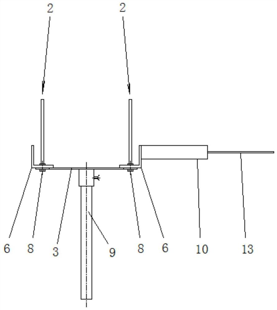
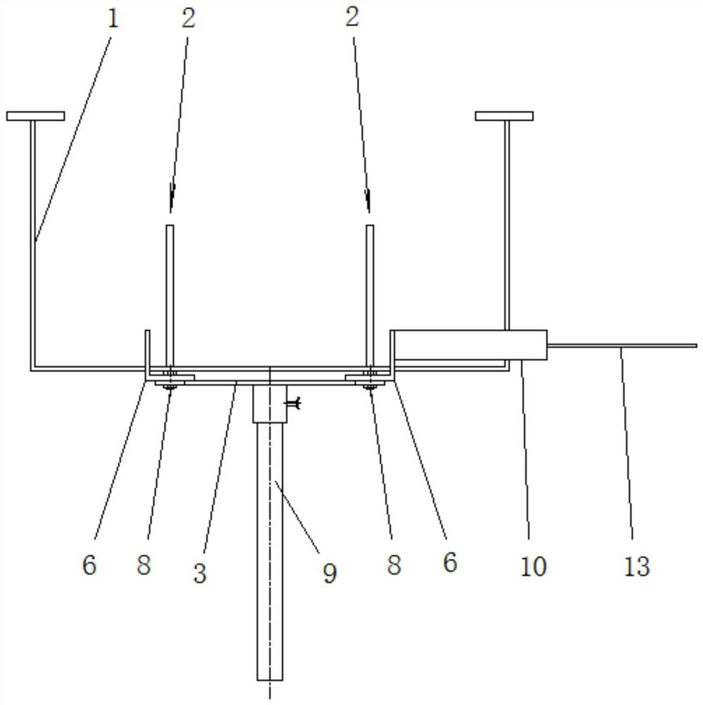
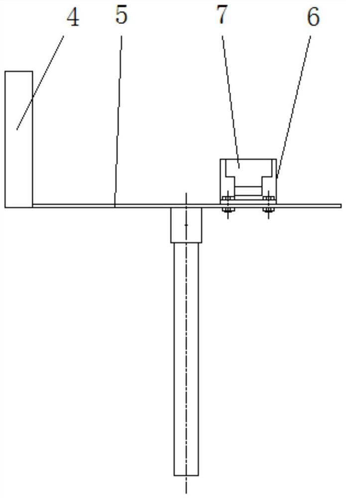
[0035] like Figures 1 to 8 Shown is an embodiment of an installation tool for a cable binding frame of the present invention, comprising a pair of L-shaped brackets 2 and an intermediate beam 3 connected between the pair of L-shaped brackets 2, each of the L-shaped brackets 2. It is formed by the right angle butt joint of a vertical positioning vertical beam 4 and a horizontal guide rail beam 5. Each guide rail beam 5 is provided with a slide seat 6 sliding along the direction of the guide rail. The upper end of the slide seat 6 is provided with a useful In the positioning groove 7 where the cable binding frame 1 is placed, a slide groove 6 is arranged on...


PUM


Abstract

The invention relates to the technical field of installation tools, in particular to a cable binding frame installation tool which comprises a pair of L-shaped supports and a middle beam connected between the pair of L-shaped supports, each L-shaped support is formed by a vertically-arranged positioning vertical beam and a horizontally-arranged guide rail beam in a right-angle butt joint mode. A sliding seat is arranged on each guide rail beam in a sliding mode in the guide rail direction, a positioning groove used for containing a cable binding frame is formed in the upper end of each sliding seat, sliding grooves are formed in the guide rail beams in the guide rail direction, and the sliding seats are fixed to the guide rail beams through bolts penetrating through the sliding grooves. High-precision installation and high-efficiency installation of the cable binding frame are achieved, and safety is good.

Description

technical field [0001] The invention relates to the technical field of installation tools, in particular to an installation tool for a cable binding frame. Background technique [0002] In ship construction, the cable binding frame is a necessary accessory for cable laying, and it is welded to the hull steel structure in the form of electric welding. During the construction, there is often an upward welding posture. During the upward welding, the person is placed under the lowering of the lashing frame, and may be injured by welding spatter. At the same time, due to the high height of the welding part, it is necessary to use scaffolding to reach it, which may cause slipping and falling. The risk, and the process also requires that the distance between each binding seat is equal, and the horizontal direction is in a straight line. [0003] In view of the above problems, it is necessary to realize the high-precision installation and high-efficiency installation of the cable b...

Claims


Application Information

Patent Timeline
IPC IPC(8): B63B73/60
CPCB63B73/60
Inventor 许文进周国伟
Owner CHENGXI SHIPYARD
Why Eureka
Try Eureka