Multi-channel circulating oil supply valve

A technology of circulating oil supply and core rotation, applied in multi-port valves, valve details, valve devices, etc., can solve the problems of limited space on site, inability to achieve oil injection point flow, unacceptable to users, etc., and achieve good expansion effect.

Pending Publication Date: 2021-07-20
周一平 +1
View PDF1 Cites 0 Cited by
  • Summary
  • Abstract
  • Description
  • Claims
  • Application Information

AI Technical Summary

Problems solved by technology

[0002] The Chinese patent ZL201410136561.4 discloses a quantitative liquid supply device. After years of application, this patent has achieved certain effects. However, in the face of different customers and different equipment, there are more or less oil injection points in the project. There are more than 1,000, according to the quantitative oil supply of one valve at one point, the valve group (quantitative liquid supply device) needs thousands of sets, so, first, the total cost of system investment is too high, which makes it unacceptable for users; second, the site space area is limited instead of allowing
Secondly, if you want to combine a progressive distributor with one-inlet and multiple-outlets and a quantitative liquid supply device, this mode cannot randomly change the flow rate of the oil injection point within the range of the combination area.

Method used


Image

  • Multi-channel circulating oil supply valve
  • Multi-channel circulating oil supply valve
  • Multi-channel circulating oil supply valve

Examples


Embodiment 1

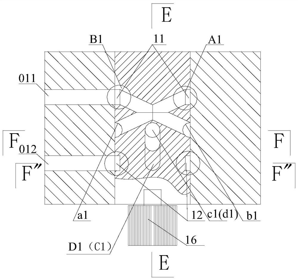
[0036] Such as Figures 5 to 9 As shown, the multi-channel oil supply valve in this embodiment includes a rotor and a stator with a rotor cavity, and the rotor is rotated in the rotor cavity, and the inner wall of the rotor cavity and the outer wall of the rotor are liquid Seal fit.

[0037] The rotating core includes a liquid circuit mechanism, and the liquid circuit mechanism includes a liquid inlet unit and a liquid outlet unit.

[0038] The liquid inlet unit includes a liquid inlet structure, and the liquid inlet structure includes a group of liquid inlet channels and a liquid inlet annular groove 11 arranged on the rotating core, and the liquid inlet annular groove is arranged at the On the same cross-section of the outer wall at one end of the core, the liquid inlet channel is composed of two cross-connected liquid inlet pipes on the rotor core, wherein the liquid inlets B1 and A1 of the two liquid inlet pipes are opposite to each other. It is arranged in the liquid in...

Embodiment 2

[0054] As a modification of Embodiment 1, the length of the rotor core and the stator is doubled, and the liquid inlet unit and a liquid outlet unit are mirrored on the other side of the rotor core; as Figure 10 and Figure 11 As shown, a form of one-input and four-outlets can be formed in which liquid enters the middle and outputs at both ends.

Embodiment 3

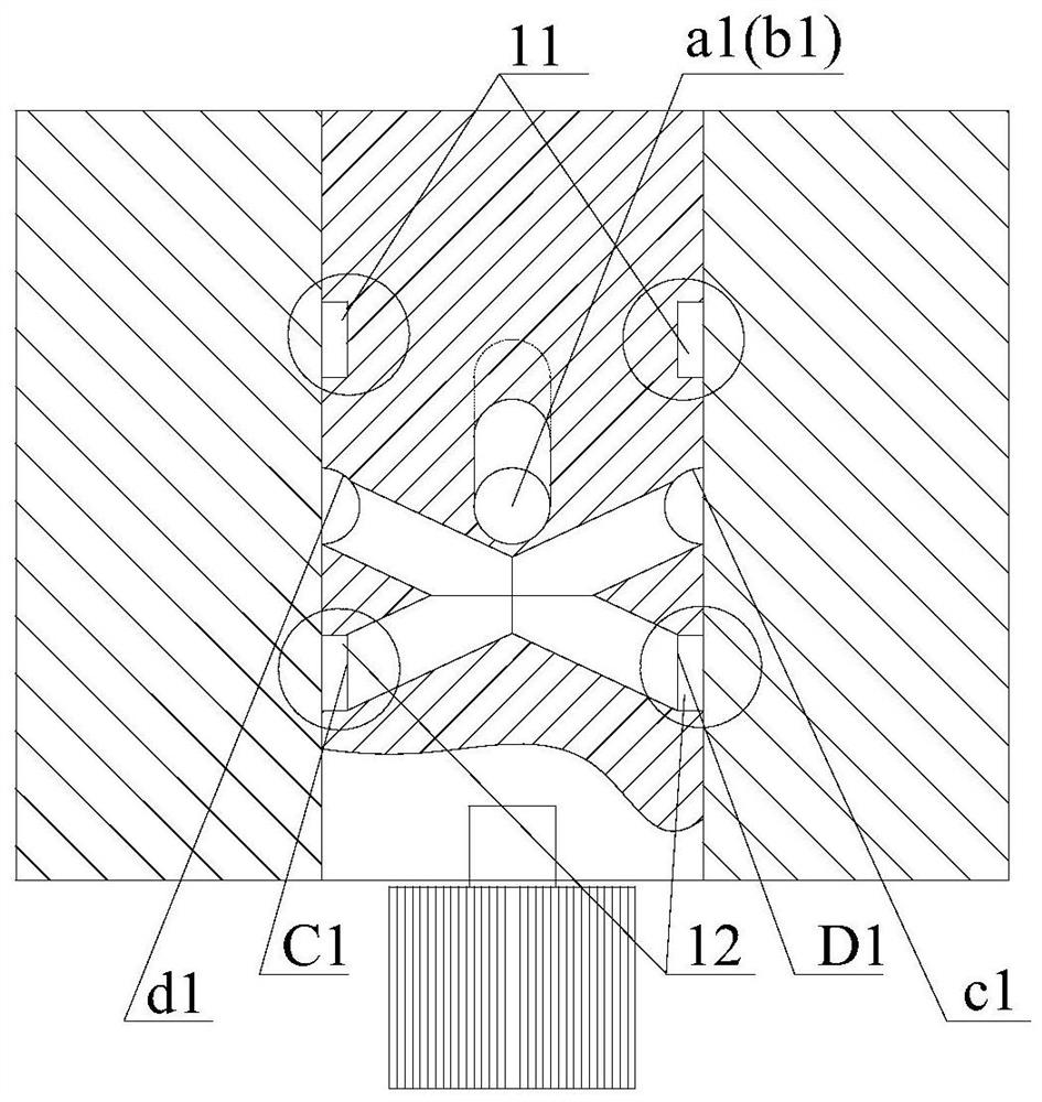
[0056] Such as Figure 12 and Figure 13 As shown, in this embodiment, the angle formed between the line between the liquid inlets of the two liquid outlet pipes and the line between the liquid outlets of the two liquid inlet pipes is 45 degrees. It has 4 outlets correspondingly, which can supply oil to 4 points at the same time. Its specific structure is as follows:

[0057] It includes a rotating core and a stator with a rotating core cavity, the rotating core is rotatably arranged in the rotating core cavity, and the inner wall of the rotating core cavity and the outer wall of the rotating core are liquid-tightly matched.

[0058] The rotating core includes a liquid circuit mechanism, and the liquid circuit mechanism includes a liquid inlet unit and a liquid outlet unit.

[0059] The liquid inlet unit includes a liquid inlet structure, and the liquid inlet structure includes a group of liquid inlet channels and a liquid inlet annular groove 11 arranged on the rotating co...


PUM


Abstract

The invention discloses a multi-channel circulating oil supply valve. The oil supply valve comprises a rotating core and a stator arranged on the rotating core in a sleeved mode, the outer wall of the rotating core is in liquid sealing fit with the stator, a metering cavity is formed in the stator, a piston is arranged in the metering cavity and divides the metering cavity into a first cavity and a second cavity, 4N liquid passing openings are formed in the peripheral side of the inner wall of a rotating core cavity at equal intervals, 4N liquid outlets are formed in the peripheral side, corresponding to the section where the liquid outlets of a liquid-outlet pipe are located, of the inner wall of the rotating core cavity at equal intervals, 2N outlets are formed in the stator, every two opposite liquid outlets communicate with one outlet through a pipeline, and a rotating control device controls the rotating core to rotate 360/4N degrees each time. According to the oil supply valve, an oil-outlet annular groove in the outer diameter of an original rotating core is omitted, then multiple sets of oil-outlet pore channels are formed in the position of the original annular groove, namely the stator (a valve body) matched with the original annular groove, and one-valve multi-point quantitative oil supply can be achieved through the multiple sets of oil-outlet pore channels.

Description

technical field [0001] The invention relates to a multi-channel circulating oil supply valve. Background technique [0002] The Chinese patent ZL201410136561.4 discloses a quantitative liquid supply device. After years of application, this patent has achieved certain effects. However, in the face of different customers and different equipment, there are more or less oil injection points in the project. There are more than 1,000, according to the quantitative oil supply of one valve at one point, the valve group (quantitative liquid supply device) needs thousands of sets, so, first, the total cost of system investment is too high, which makes it unacceptable for users; second, the site space area is limited and not allowed. Secondly, if you want to use a progressive distributor with one in and multiple out to combine with a quantitative liquid supply device, this mode cannot realize the random change of the flow rate of the oil injection point within the range of the combina...

Claims


Application Information

Patent Timeline
Patent Type & Authority Applications(China)
IPC IPC(8): F16K11/085F16K21/00F16K27/06F16K31/04F16N25/04
CPCF16K11/085F16K21/00F16K27/065F16K31/041F16N25/04
Inventor 周一平周健帅
Owner 周一平
Why Eureka
Try Eureka