
Anti-freezing device for faucet

A technology of antifreeze device and faucet, which is applied in the direction of valve device, valve operation/release device, pipe/pipe joint/pipe fitting, etc. It can solve the problem that the faucet cannot be equipped with thermal insulation structure, etc., and achieve internal structure design for drainage antifreeze, convenient operation, Sophisticated effect

Inactive Publication Date: 2021-07-20
SHANGHAI GREEN SUN ARCHITECTURE HARDWARE CO LTD
View PDF0 Cites 0 Cited by
  • Summary
  • Abstract
  • Description
  • Claims
  • Application Information

AI Technical Summary

Problems solved by technology

[0002] Faucet is the popular name of water valve, which is used to control the size of the water flow and has the effect of saving water. The replacement speed of faucets is very fast, from old-fashioned cast iron technology to electroplating knob type, and to stainless steel single-temperature single-control faucet , stainless steel dual-temperature dual-control faucet, kitchen semi-automatic faucet, now, more and more consumers choose faucets, they will comprehensively consider materials, functions, shapes and other aspects. Compared with water pipes, faucets are external accessories. In the cold winter, the outside of the water pipe can be wrapped with a thick insulation layer to avoid freezing, but the faucet cannot be equipped with an insulation structure. The existing faucets are all vertically blocked, and the valve cannot store water empty, so it is impossible to prevent the faucet from freezing. problems, which have brought great inconvenience to production and life

Method used


Image

  • Anti-freezing device for faucet
  • Anti-freezing device for faucet
  • Anti-freezing device for faucet

Examples


Embodiment Construction

[0015] The following will clearly and completely describe the technical solutions in the embodiments of the present invention with reference to the accompanying drawings in the embodiments of the present invention. Obviously, the described embodiments are only some, not all, embodiments of the present invention. Based on the embodiments of the present invention, all other embodiments obtained by persons of ordinary skill in the art without making creative efforts belong to the protection scope of the present invention.

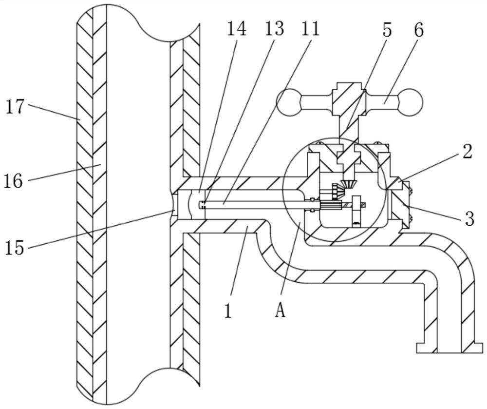
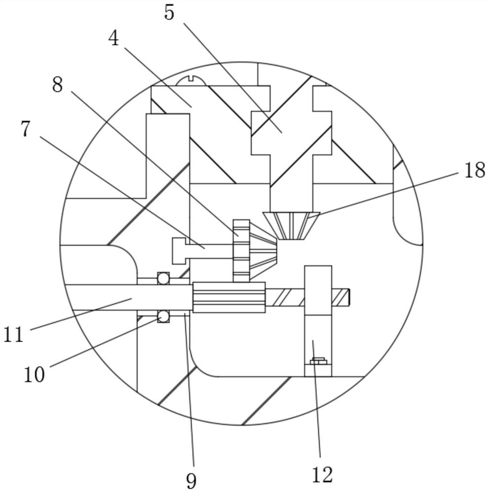
[0016] see Figure 1-3 , the present invention provides a technical solution: a faucet antifreeze device, including an elbow 1 and a valve body 2, one end of the elbow 1 is welded on a water pipe 16, and the outer side of the water pipe 16 is provided with a heat preservation sleeve 17, and the water pipe 16 is connected to the elbow. An overflow port 15 is opened on the opposite side wall of the pipe 1, a valve body 2 is fixedly connected to the outer wall of...


PUM


Abstract

The invention discloses an anti-freezing device for a faucet. The anti-freezing device comprises an elbow pipe and a valve body, wherein one end of the elbow pipe is welded to a water pipe; the water pipe is sleeved with a heat preservation sleeve; an overflow port is formed in the side wall, opposite to the elbow pipe, of the water pipe; the valve body is fixedly connected to the outer wall of the elbow pipe; a side valve plug is embedded into one side of the valve body; an upper valve plug is embedded into the upper side of the valve body; a regulating valve stem is rotationally embedded into the upper valve plug; and a handle is fixedly connected to the top end of the regulating valve stem. The anti-freezing device for the faucet has the advantages of being reasonable in internal structural design and capable of draining water and preventing freezing; in the using process, through the arrangement of a mechanical structure in the valve body, driving steering is achieved, the anti-freezing device conforms to the using habit of the faucet and is convenient to operate; and the mechanical structure can adjust the position of a rubber piston in the elbow pipe in real time to change the open / close state of the faucet, when the rubber piston penetrates into the elbow pipe, stored water in the elbow pipe can be completely squeezed into the water pipe, and the stored water is in a heat preservation state.

Description

technical field [0001] The invention relates to an antifreeze device, in particular to an antifreeze device for a faucet, which belongs to the field of hardware. Background technique [0002] Faucet is the popular name of water valve, which is used to control the size of the water flow and has the effect of saving water. The replacement speed of faucets is very fast, from old-fashioned cast iron technology to electroplating knob type, and to stainless steel single-temperature single-control faucet , stainless steel dual-temperature dual-control faucet, kitchen semi-automatic faucet, now, more and more consumers choose faucets, they will comprehensively consider materials, functions, shapes and other aspects. Compared with water pipes, faucets are external accessories. In the cold winter, the outside of the water pipe can be wrapped with a thick insulation layer to avoid freezing, but the faucet cannot be equipped with an insulation structure. The existing faucets are all ver...

Claims


Application Information

Patent Timeline
Patent Type & Authority Applications(China)
IPC IPC(8): F16K27/04F16K31/53F16L59/16
CPCF16K27/041F16K31/53F16L59/16
Inventor 黄琪华
Owner SHANGHAI GREEN SUN ARCHITECTURE HARDWARE CO LTD
Learn More