Rotor punching sheet, rotor and permanent magnet direct drive motor

A rotor punching and rotor technology, which is applied in the field of permanent magnet motors, can solve the problems of increasing the amount of magnetic steel, rotor flux leakage, and low motor power density, so as to reduce rotor flux leakage, reduce material costs, and improve performance parameters. and the effect of motor power density

Pending Publication Date: 2021-07-20
北京明诚环保科技有限公司 +1
View PDF0 Cites 0 Cited by
  • Summary
  • Abstract
  • Description
  • Claims
  • Application Information

AI Technical Summary

Problems solved by technology

However, after the number of poles increases, it is difficult to increase the amount of surface mount and radial magnetic circuit structure magnets, resulting in low power density of the motor. Therefore, the use of radial magnetic circuit structure to increase the power density of the motor has become the preferred solution.
[0005] When the radial magnetic circuit structure is used, in order to ensure the structural strength of the rotor of the motor, it is usually necessary to have a wider magnetic isolation magnetic bridge to ensure the overall structural strength of the rotor punching piece. However, the smaller the width of the magnetic isolation magnetic bridge, the magnetic The more saturated the pass, the better the effect of limiting magnetic flux leakage. The wider magnetic isolation magnetic bridge brings the problem of rotor magnetic flux leakage, which not only increases the amount of magnetic steel, but also reduces the design power density of the motor.

Method used


Image

  • Rotor punching sheet, rotor and permanent magnet direct drive motor
  • Rotor punching sheet, rotor and permanent magnet direct drive motor
  • Rotor punching sheet, rotor and permanent magnet direct drive motor

Examples


Embodiment Construction

[0034] In order to make the purpose, technical solutions and advantages of the embodiments of the present invention more clear, the technical solutions of the embodiments of the present invention will be clearly and completely described below in conjunction with the drawings of the embodiments of the present invention. Apparently, the described embodiments are some, not all, embodiments of the present invention. Based on the described embodiments of the present invention, all other embodiments obtained by persons of ordinary skill in the art without creative efforts shall fall within the protection scope of the present invention.

[0035] Unless otherwise defined, the technical terms or scientific terms used in the present invention shall have the usual meanings understood by those skilled in the art to which the present invention belongs. "First", "second" and similar words used in the present invention do not indicate any order, quantity or importance, but are only used to d...


PUM


Abstract

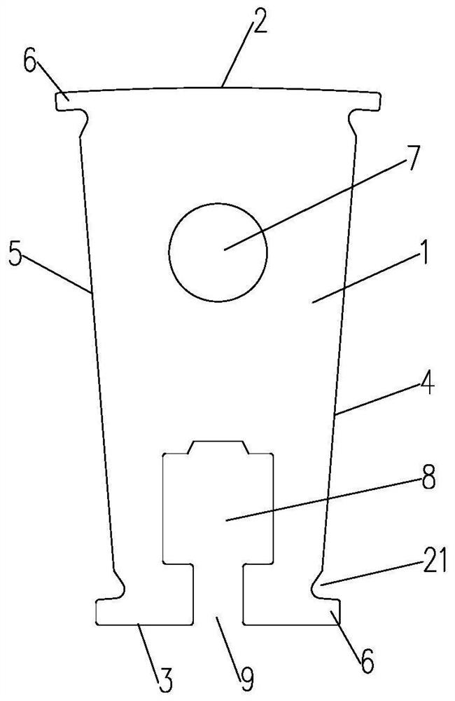
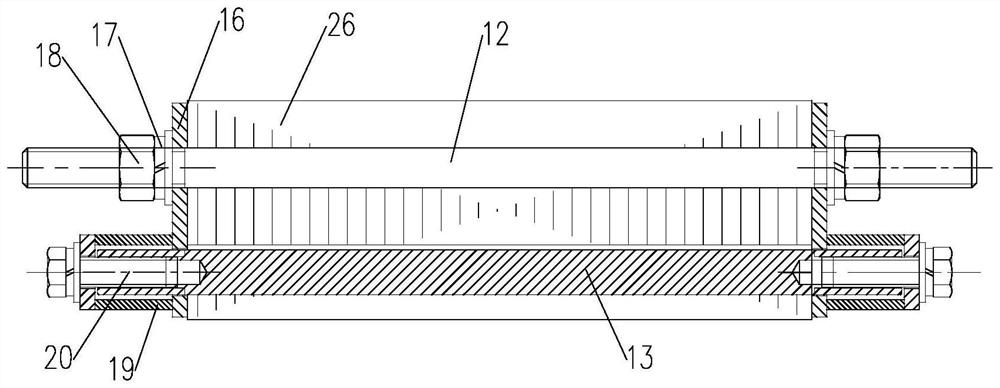
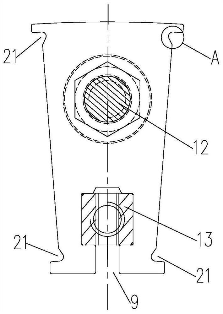
The embodiment of the invention provides a rotor punching sheet, a rotor and a permanent magnet direct drive motor. The rotor punching sheet comprises a sheet body, the sheet body is provided with an outer periphery and an inner periphery which are opposite to each other, and a first side and a second side which are connected with one end of the outer periphery and one end of the inner periphery which are located on the same side, wherein the first side and the second side are symmetrically arranged, the outer periphery is a cambered surface, the length of the outer periphery is greater than that of the inner periphery; the sheet body forms a fan shape with four vertex angles; the four vertex angles of the sheet body protrude outwards in the circumferential direction of the sector to form protruding parts. The sheet body is provided with a first connecting hole and a second connecting hole. The rotor punching sheet provided by the embodiment of the invention is fan-shaped, the rotor is formed by splicing a plurality of sectors (rotor iron core teeth), the sectors are not connected by a magnetic isolation magnetic bridge, the magnetic leakage of the rotor is reduced, and the plurality of sectors are spliced to form a multi-pole tangential magnetic circuit structure, so that the performance parameters and the power density of the motor can be greatly improved, and the material cost of the motor is reduced.

Description

technical field [0001] The invention belongs to the technical field of permanent magnet motors, in particular to a rotor punch, a rotor and a permanent magnet direct drive motor. Background technique [0002] At present, there are more and more applications of direct-drive motors in the permanent magnet motor industry. The solution of replacing high-speed motor acceleration and deceleration devices with permanent magnet low-speed direct-drive motors has become a hot spot in the transformation of the motor application industry. Compared with low-speed motors with the same power, high-speed motors are small in size and center height. During the design of the transformation plan, it may be limited by the installation environment. It is required that the volume of the low-speed direct drive motor be as small as possible, and the center height should not be too high. Therefore, permanent magnet direct drive motors with high power density have become the first products at this sta...

Claims


Application Information

Patent Timeline
Patent Type & Authority Applications(China)
IPC IPC(8): H02K1/22H02K1/24H02K1/27H02K1/28H02K21/02
CPCH02K1/22H02K1/24H02K1/2706H02K1/272H02K1/2773H02K1/28H02K21/028
Inventor 梅洛明鲁方春片亨范尚健石飞虎
Owner 北京明诚环保科技有限公司
Why Eureka
Try Eureka