System for modeling 3D scene from single design picture

A picture modeling and 3D technology, applied in the field of computer vision, can solve problems such as wasting time, achieve the effect of reducing construction time and speeding up construction

Pending Publication Date: 2021-07-23
上海随幻智能科技有限公司
0 Cites 0 Cited by

AI-Extracted Technical Summary

Problems solved by technology

And for another application scene, although the previous object materials ca...

Abstract

The invention relates to the technical field of computer vision, in particular to a system for modeling a 3D scene from a single design picture. The method comprises the following steps: rendering: randomly arranging objects in a rendering engine to obtain a rendering result graph and a data set of a 3D object transformation matrix of each object; model extraction: extracting a prediction model from the data set by using a deep learning network; instance segmentation: inputting a single scene design picture, and predicting an instance segmentation result and a transformation matrix of a 3D object of each instance; and modeling: placing an object corresponding to a single instance in a scene under the guidance of the transformation matrix to complete result modeling. According to the method, instance segmentation is performed by using the deep neural network MaskR-CNN to obtain the images of a 2D object bounding box and a bounding box area, and the 3D scene arrangement is automatically completed by a single design picture according to the 2D plane mapping of the 3D object corresponding to the instance segmentation result, so that the scene construction time can be greatly shortened, and the scene construction speed is increased.

Application Domain

Technology Topic

Image

  • System for modeling 3D scene from single design picture
  • System for modeling 3D scene from single design picture
  • System for modeling 3D scene from single design picture

Examples

  • Experimental program(1)

Example Embodiment

[0046] Example 1
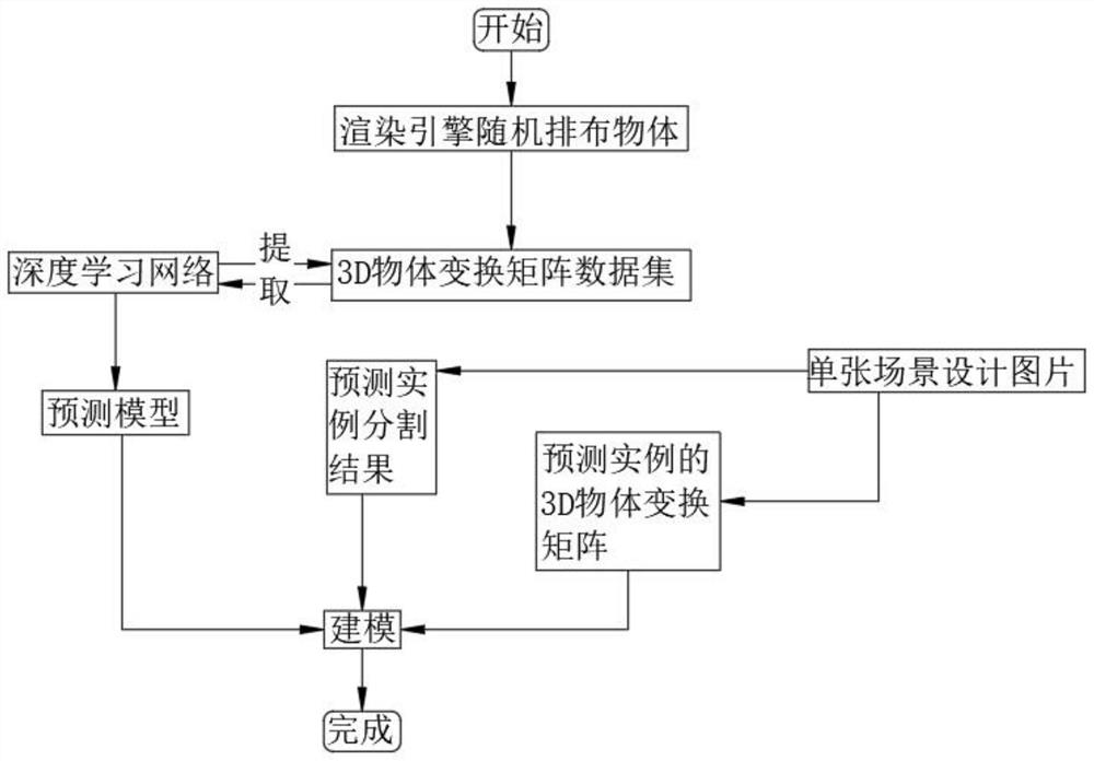
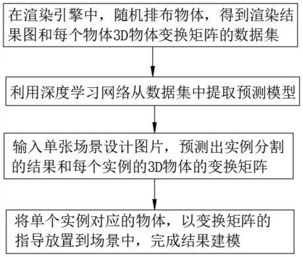
[0047] The present invention provides a system for modeling 3D scenes from a single design picture, please refer to Figure 1-Figure 3 , including the following steps:
[0048] Rendering: In the rendering engine, objects are randomly arranged to obtain the rendering result map and the data set of the 3D object transformation matrix of each object;
[0049] Extracting models: using deep learning networks to extract predictive models from datasets;
[0050] Instance segmentation: Input a single scene design picture, predict the result of instance segmentation and the transformation matrix of the 3D object of each instance;
[0051] Modeling: Place the object corresponding to a single instance into the scene with the guidance of the transformation matrix to complete the result modeling.
[0052] Further, the data set adopts the InGame loading material method, and the method steps are as follows:
[0053] Randomly load models from the model library and place them;
[0054] render the result graph;
[0055] generate synthetic datasets;
[0056] In the construction of the dataset, the UE4 game engine is used for rendering.
[0057] At the same time, when building a dataset, the scene used does not contain the requirement of predicting 3D from 2D pictures of natural scenes. Therefore, when building a dataset, it is not necessary to collect a large number of 3D materials that can describe everything in nature, and the input picture is The 2D flat scene design diagram given by the UI designer, at this time, the material of the 3D object will not exceed the scope of the model library.
[0058] Among them, a single scene design picture is input, and a deep neural network method is used to segment the picture to obtain an image of the 2D object bounding box and the bounding box area.
[0059] Instance segmentation uses the deep neural network Mask R-CNN to segment the images. The segmentation steps are as follows:
[0060] Image input: input the image to be detected;
[0061] Area suggestion: Select the area frame for the image input in the first step. The commonly used method is to selectively search for the frame. It mainly uses the edge, texture, color, color change and other information of the image to select the area that may contain objects in the image. ;
[0062] Feature extraction: Use the CNN network to extract features from the potential regions where objects exist; when the sizes of the images extracted in the region selection are different, but the feature scales output after convolution are the same, the regions are suggested to be selected regions. It is scaled to a uniform size of 227x227, and then sent to CNN for feature extraction; the network used for R-CNN feature extraction is the basic network model obtained by pre-training the CNN model of AlexNet on ImageNet, and then the network needs to be processed. fine-tune, others use AlexNet's network structure fine-tune, including five layers of convolution and two layers of fully connected layers;
[0063] SVM classification: The extracted features are sent to the SVM classifier to obtain a classification model, and each category corresponds to an SVM classifier, and the classifier of each category determines the category of the feature;
[0064] Border regression: The image area suggested by the correction area, and the category of each image area corresponds to a regression model; the border regression is mainly for accurate positioning, what it does is to put the old area Remap to new area In, center position (x, y) - width and height dimension (w, h);
[0065]
[0066]
[0067] where, t x , t y , t w , t h respectively The proportional relationship in Cartesian and polar coordinates, W * T φ 5 (P i ) is the correction value of the position, W * is the adjusted area;
[0068] Use non-maximum suppression output: When several regions select objects in the same region, use non-maximum suppression LOU ≥ 0.5 to obtain a subset of regions without redundancy, including the following steps:
[0069] All regional scores are arranged in descending order;
[0070] Redundancy is eliminated, and all areas with the maximum score area LOU ≥ 0.5; the closer the value of IoU is to 1, the closer the two areas are to coincidence, that is to say, the two candidate areas predict the same target.
[0071] The maximum score area is reserved, and the remaining area is used as a new candidate set.
[0072] Further, the steps of CNN network feature extraction are as follows:
[0073] Input the whole picture into CNN to get the feature map;
[0074] Find the mapping patch of each candidate box on the feature map, and input this patch as the convolution feature of each candidate box to the SPP layer and subsequent layers;
[0075] The features in the feature map are extracted by mapping patches.
[0076] Specifically, the formula corresponding to the category of the image area and the regression model is as follows:
[0077]
[0078] where x i is the eigenvalue group of the candidate region, y i is the target value group, T is the approximation degree, is the average of the feature values ​​of the candidate regions, is the average of the target values. When T is closer to 1, the similarity between the category of the image region and the regression model is less, and the corresponding matching failure rate is higher. When T is farther from 1 and closer to 0, the similarity between the category of the image region and the regression model is greater, and the corresponding matching is successful. the higher the rate.
[0079] In addition, the steps of the transformation matrix of the 3D object are as follows:
[0080] Obtain the structure of instance segmentation, and use the deep learning network PoseNet to map each instance segmentation result to a 3D object;
[0081] 2D plane mapping after rotation, displacement, scaling and occlusion of 3D objects;
[0082] Calculate the coordinate values ​​of the 3D object:
[0083] Further, the transformation matrix formula for calculating the coordinate value of the 3D object is:
[0084]
[0085] where C -1 is the transformation matrix of the camera, U x , U y , U z , V x , V y , V z , N x , N y , N z is the coordinates in the base point of U, V, and N in the UVN system, and T is the translation transformation coefficient.
[0086] Specifically, the modeling steps are as follows:
[0087] Get the coordinate value of the 3D object;
[0088] The object corresponding to a single instance is placed in the scene according to the guidance of the coordinate value of the transformation matrix.

PUM

no PUM

Description & Claims & Application Information

We can also present the details of the Description, Claims and Application information to help users get a comprehensive understanding of the technical details of the patent, such as background art, summary of invention, brief description of drawings, description of embodiments, and other original content. On the other hand, users can also determine the specific scope of protection of the technology through the list of claims; as well as understand the changes in the life cycle of the technology with the presentation of the patent timeline. Login to view more.

Similar technology patents

Rapid construction method of program white list

ActiveCN114579967AReduced build timeDigital data authenticationPlatform integrity maintainanceWhitelistInstruction step
Owner:北京珞安科技有限责任公司

Epidermis skin model with melanin and construction method and application of epidermis skin model

PendingCN111117945ASimplify the operation processReduced build timeCulture processEpidermal cells/skin cellsStratum basaleCell layer
Owner:GUANGDONG BOXI BIO TECH CO LTD

Establishment method of three-dimensional cell model

PendingCN105671029AEasy to operateReduced build timeCulture processElectrical/wave energy microorganism treatmentBiologyFerromagnetism
Owner:THE SIXTH AFFILIATED HOSPITAL OF SUN YAT SEN UNIV

Gingival epithelium model and in-vitro building method thereof

InactiveCN107312743AGood repeatabilityReduced build timeCulture processEpidermal cells/skin cellsPhases of clinical researchStructure and function
Owner:GUANGDONG BOXI BIO TECH CO LTD

Classification and recommendation of technical efficacy words

  • Build fast
  • Reduced build time

Subsequent docking process of self-elevating platform pile shoe

ActiveCN104386219AGood build stabilityBuild fastDry-dockingButt jointMarine engineering
Owner:舟山长宏国际船舶修造有限公司

Multi-light-source acceleration method for programmable shader

ActiveCN104463943AImprove efficiencyReduced build time3D-image renderingTree shapedShader
Owner:合肥月照数码科技有限公司
Why Eureka
Try Eureka