Multi-station milling fixture equipment

A multi-station, milling technology, applied in the direction of metal processing equipment, manufacturing tools, clamping, etc., can solve problems such as uneven force, deformation of the hole wall to the outer surface, etc., to achieve reliable clamping and ensure clamping effect Effect

Active Publication Date: 2021-07-23
宁波创世轴业有限公司
View PDF5 Cites 0 Cited by
  • Summary
  • Abstract
  • Description
  • Claims
  • Application Information

AI Technical Summary

Problems solved by technology

[0004] The present invention provides a multi-station milling fixture device, which has the beneficial effect of uniform clamping force, and solves the problem that the existing fixture clamps when the multi-station milling fixture device mentioned in the above background technology clamps hole parts. When the force is uneven, the problem of deformation from the hole wall to the outer surface will occur.

Method used


Image

  • Multi-station milling fixture equipment
  • Multi-station milling fixture equipment
  • Multi-station milling fixture equipment

Examples


Embodiment 1

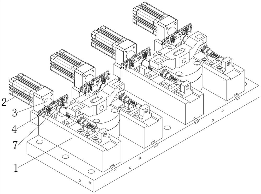
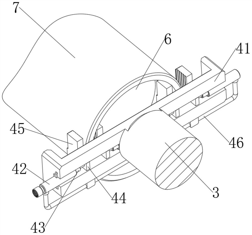
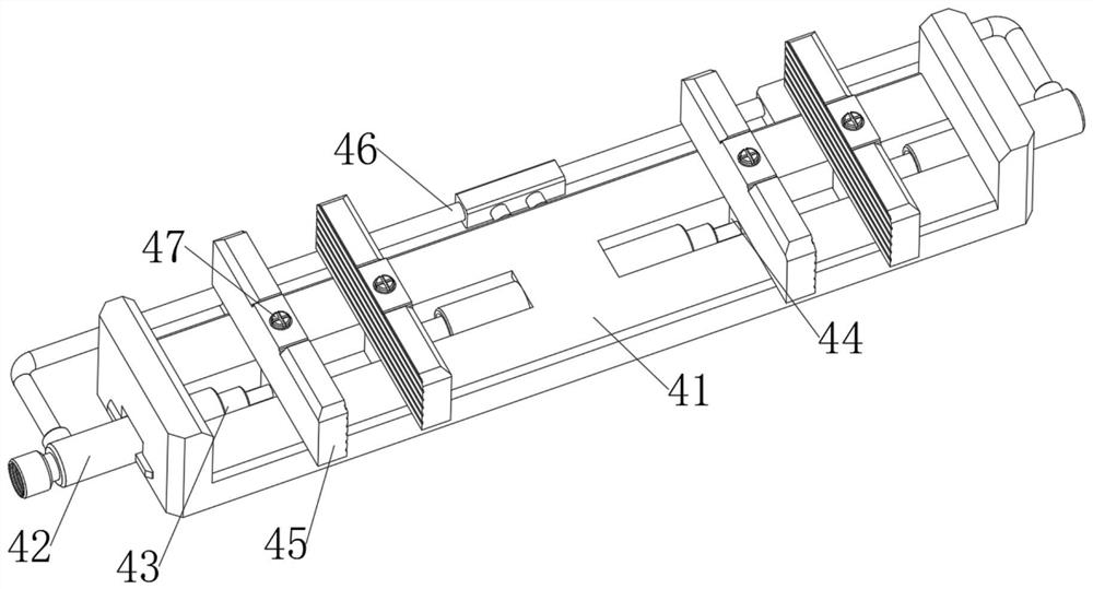
[0028] see Figure 1-3 , a multi-station milling fixture device, including a station seat 1 and an outer cylinder 2 on the station seat 1, a push rod 3 is slidably connected to the outer cylinder 2, and a clamping device 4 is installed on the push rod 3 to clamp Device 4 comprises clamping seat 41, and clamping seat 41 is fixedly installed on the push rod 3, and supporting device 42 is fixedly installed on clamping seat 41, and the inside of supporting device 42 is slidingly connected with pushing device 43, and pushing device 43 is installed with Sliding plate 44, on the sliding plate 44, the clamping plate 45 that is threadedly connected with clamping parts by threaded rod 47;

[0029] The support device 42 includes an outer sleeve 421, the outer sleeve 421 is fixed on the clamping seat 41, the outer sleeve 421 is equipped with a trachea 46, the outer sleeve 421 is provided with a circular hole groove 422, and the trachea 46 communicates with the inside of the circular hole ...

Embodiment 2

[0033] This embodiment is an improvement made on the basis of Embodiment 1. The pushing device 43 includes a shaft 431, the shaft 431 is slidably connected inside the round hole groove 422, and a sliding groove 434 is arranged in the shaft 431. The sliding groove 434 The inside is movably connected with the adjusting device 5, and the sliding groove 434 is also slidably connected with the moving block 433 of the limit adjusting device 5, the block 433 is connected with the shaft rod 431 through the limit spring 8, and the block 433 and the adjusting device 5 are perpendicular to each other. And the clamping block 433 is in conflict with the adjusting device 5 , and the clamping block 433 is in conflict with the inner wall of the round hole groove 422 .

[0034] In this example:

[0035] Reduce springback: According to Figure 4 and Figure 5As shown, the shaft 431 inside the round hole groove 422 is pushed by high-pressure gas, so that the shaft rod 431 slides inside the rou...

Embodiment 3

[0038] This embodiment is an improvement made on the basis of Embodiment 2. The adjustment device 5 includes a telescopic rod 51, which is slidably installed inside the slide groove 434, and the telescopic rod 51 is connected with the slide plate 44. On the telescopic rod 51 A connecting rod 53 is rotatably connected, and the connecting rod 53 is connected with the sliding groove 434 by a compression spring 54. The limit block 52 is also fixedly installed on the telescopic rod 51. The inner wall of the shaft rod 431 is provided with a spiral groove 447, and the shaft rod 431 is also provided with a The vertical groove 446 and the spiral groove 447 are in communication with the vertical groove 446 , and the inside of the outer casing 421 is provided with a chute 423 .

[0039] In this example:

[0040] Precise fixation: according to Figure 4 As shown, although the rebound distance of the shaft rod 431 can be reduced by using Embodiment 2, the problem of rebound is not solved....


PUM


Abstract

The invention relates to the technical field of milling fixtures, in particular to multi-station milling fixture equipment. The multi-station milling fixture equipment comprises station seats and outer cylinders on the station seats, wherein push rods are slidably connected to the outer cylinders; clamping devices are mounted on the push rods; the clamping devices comprise clamping seats; the clamping seats are fixedly mounted on the push rods; supporting devices are fixedly mounted on the clamping seats; pushing devices are slidably connected to the interiors of the supporting devices; sliding plates are mounted on the pushing devices; clamping plates for clamping parts are in threaded connection with the sliding plates through threaded rods; the supporting devices comprise outer sleeves; and the outer sleeves are fixed to the clamping seats. According to the multi-station milling fixture equipment, the clamping devices are arranged to be matched with the pushing devices, and machined parts are clamped through the oppositely-arranged clamping devices, so that clamping is firm, the stress on the inner walls of grooves and the stress on the outer surfaces of the machined parts are uniform and equal, and the situation that the machined parts are deformed due to uneven clamping stress is avoided.

Description

technical field [0001] The invention relates to the technical field of milling fixtures, in particular to a multi-station milling fixture device. Background technique [0002] With the rapid development of social economy, milling fixtures are mainly used to process planes, grooves, splines and various forming surfaces on parts. It is one of the most commonly used fixtures, mainly composed of positioning devices, clamping devices, clamping bodies, It is composed of connecting elements and tool setting elements. During milling, the cutting force is large, and the cutting is intermittent, and the vibration is large. Therefore, the clamping force of the milling machine fixture is relatively high, and the rigidity and strength of the fixture are relatively high. [0003] However, when the existing multi-station milling fixture equipment clamps a part with a groove inside, and a thin wall is formed between the groove and the part, then there will be insufficient internal and exter...

Claims


Application Information

Patent Timeline
Patent Type & Authority Applications(China)
IPC IPC(8): B23Q3/00
CPCB23Q3/00
Inventor 王振
Owner 宁波创世轴业有限公司
Why Eureka
Try Eureka