
Wall perforating device for indoor decoration

A technology of punching device and interior decoration, applied in stone processing tools, work accessories, manufacturing tools, etc., can solve problems such as low efficiency and construction workers inhalation, and achieve the effect of avoiding residues and being convenient to use.

Pending Publication Date: 2021-07-23
何远兵
View PDF7 Cites 1 Cited by
  • Summary
  • Abstract
  • Description
  • Claims
  • Application Information

AI Technical Summary

Problems solved by technology

[0005] In order to overcome the shortcoming that the hand electric drill can only punch one hole at a time, the efficiency is not high, and the construction workers will inhale some dust, the technical problem to be solved is: provide an interior decoration with high drilling efficiency, which can prevent the construction workers from inhaling dust hole punching device

Method used


Image

  • Wall perforating device for indoor decoration
  • Wall perforating device for indoor decoration
  • Wall perforating device for indoor decoration

Examples


Embodiment 1

[0031] A wall punching device for interior decoration, such as figure 1 , figure 2 and image 3 As shown, it includes a car board 1, a wheel 2, a handle 3, a positioning mechanism 4, a second fixing rod 51, an electric drill 52, a switch 53, a connecting plate 54 and a second spring 55. The bottom and left sides of the car board 1 are installed with Two wheels 2, the wheel 2 is a universal wheel, a handle 3 is connected to the left side of the top of the board 1, a positioning mechanism 4 is installed on the right side of the top of the board 1, a second fixing rod 51 is connected to the upper part of the right side of the handle 3, the second An electric drill 52 is slidably provided on both the front and rear sides of the fixing rod 51 , a connecting plate 54 is installed between the left sides of the two electric drills 52 , a switch 53 is installed on the left side of the connecting plate 54 , and the two electric drills 52 are electrically connected to the switch 53 . ...

Embodiment 2

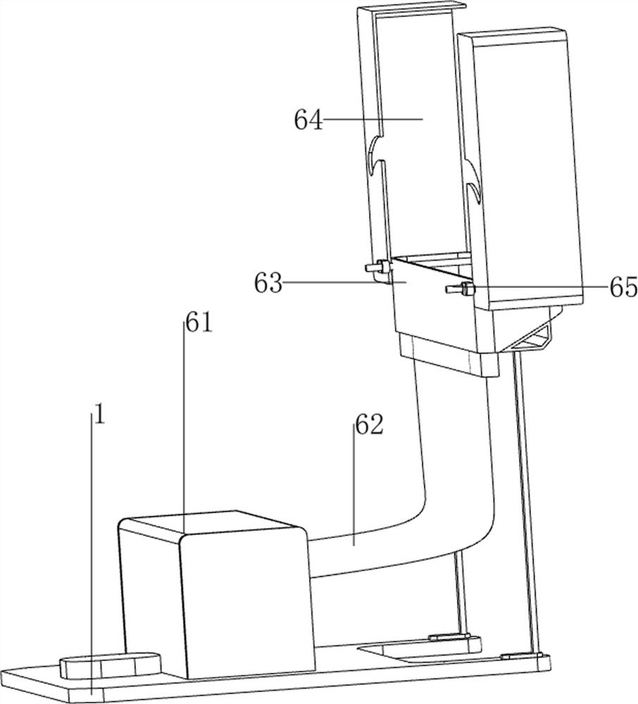
[0035] On the basis of Example 1, as figure 1 , Figure 4 , Figure 5 , Image 6 and Figure 7 As shown, it also includes a shielding mechanism 6, the shielding mechanism 6 includes a collection frame 61, a transmission pipe 62, a receiving frame 63, a baffle 64 and a first rotating shaft 65, and a collection frame 61 is provided in the middle of the top of the vehicle deck 1. The collection frame The right side of 61 is connected with a transmission pipe 62, the top right side of the car board 1 is connected with a receiving frame 63, the bottom of the receiving frame 63 is connected with the transmission pipe 62, and the front and rear sides of the receiving frame 63 are rotatably connected with a first rotating shaft 65, There is friction between the first rotating shaft 65 and the material receiving frame 63 , and baffles 64 are connected to the two first rotating shafts 65 .

[0036] When the electric drill 52 is in contact with the wall, the electric drill 52 makes h...


PUM


Abstract

The invention relates to a perforating device, in particular to a wall perforating device for indoor decoration. According to the wall perforating device for indoor decoration, the perforating efficiency is high, and building workers can be prevented from sucking dust. According to the technical scheme, the wall perforating device for indoor decoration comprises a sweeping board, wheels and a handle, and the wheels are installed on the two sides of the bottom of the sweeping board; and one side of the top of the sweeping board is connected with the handle. The wall perforating device can be more stable through a positioning mechanism, two holes can be drilled at a time through an electric drill, and the efficiency is improved; dust generated during perforating can be blocked through a blocking mechanism, and the building workers are prevented from sucking the dust; and a switch can be pressed through an auxiliary drilling mechanism, and the building workers can push the handle conveniently.

Description

technical field [0001] The invention relates to a punching device, in particular to a wall punching device for interior decoration. Background technique [0002] In the process of house construction, it is necessary to carry out interior decoration of the rough house to make the interior more beautiful and convenient for people to live in. During interior decoration, it is often necessary to install some furniture on the wall, so it is necessary to punch holes in the wall for fixing. furniture. [0003] At present, construction workers generally use a hand drill to drill holes in the wall. The hand drill can only drill one hole at a time, which is not efficient. Secondly, a lot of dust will be generated during the drilling process, and construction workers need to use their hands to drill holes. Holding a hand drill, so construction workers will inhale some dust, which will affect the health of construction workers. [0004] In view of the current problems, we have develop...

Claims


Application Information

Patent Timeline
Patent Type & Authority Applications(China)
IPC IPC(8): B28D1/14B28D7/00B28D7/02
CPCB28D1/14B28D1/146B28D7/00B28D7/005B28D7/02
Inventor 何远兵
Owner 何远兵
Learn More