Full-automatic film cutting machine for battery pole piece processing

A fully automatic technology for battery pole pieces, which is applied to machine tools, metal processing equipment, manufacturing tools, etc. suitable for grinding workpiece edges, and can solve problems such as unfavorable assembly by installers, too sharp pole piece edges, and inability to adjust cutting dies, etc.

Inactive Publication Date: 2021-07-23
马荣跃
View PDF0 Cites 0 Cited by
  • Summary
  • Abstract
  • Description
  • Claims
  • Application Information

AI Technical Summary

Problems solved by technology

[0003] In order to solve the above technical problems, the present invention provides a fully automatic film cutting machine for battery pole piece processing, to solve the problem that the existing film cutting machine cannot adjust the die cutting for the pole pieces required by different types of batteries, and cut out The edge of the pole piece is too sharp, which is not conducive to the later assembly of the installer

Method used


Image

  • Full-automatic film cutting machine for battery pole piece processing
  • Full-automatic film cutting machine for battery pole piece processing
  • Full-automatic film cutting machine for battery pole piece processing

Examples


Embodiment

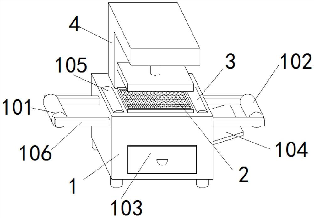
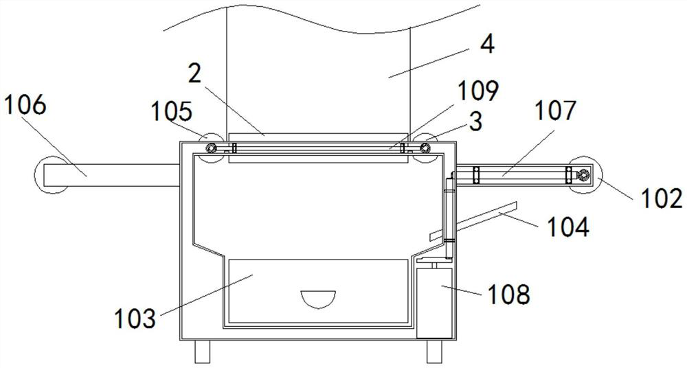
[0038] as attached figure 1 to attach Figure 15 Shown: a fully automatic film cutting machine for battery pole piece processing, including a main body 1, a raw material reel 101, a waste reel 102, and a bracket 106. The inner walls on both sides of the main body 1 are fixed with brackets 106, and the left side of the main body 1 A rotatable raw material reel 101 is provided at the end of the bracket 106, and a rotatable waste material reel 102 is provided at the end of the bracket 106 on the right side of the main body 1, and a piece extending to the inside of the main body 1 is provided under the right side bracket 106 of the main body 1. The material guide plate 104, the top center of the main body 1 is embedded with a cutting template 2, and the inner wall of the main body 1 on the left side of the cutting template 2 is embedded with a material guide shaft 105, and the top of the main body 1 opposite to the material guide shaft 105 is provided with a material rotating shaf...

Embodiment 1

[0049] Firstly, the present invention is energized as a whole, and the raw material is put into the raw material reel 101, and one end of the raw material is stretched onto the waste material rotating shaft 102 and wound around to fix it with the waste material reel 102.

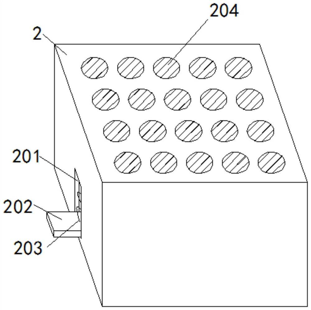
[0050] At this time, turn on the power supply of the hydraulic expansion device 401 to make it work to drive the equipment plate 402 to the cutting template 2. When the pressure film column 403 at the bottom of the equipment plate 202 contacts the cutting template 2, the cutting template 2 will move to the inside of the main body 1. For a certain distance, when the cutting template 2 is squeezed by the die cutting device 4, it will move to the inside of the main body 1 and the extension plate 202 will drive the diaphragm tube plate 205 to move upward, and the driving screw 208 in the driving ring 207 will drive the diaphragm tube 206 at the same time. The inner screw 213 rotates, and when the screw 213 rotate...

Embodiment 2

[0053] Control the retraction of the hydraulic telescopic device 401 to make the equipment plate 402 contact with the template fixing plate 211, at this time, the pressure film column 403 at the bottom of the equipment plate 402 will return to its original position under the action of the spring 406, and the cutting template 2 loses the cutting die The extrusion cutting template 2 of the device 4 will return to its original position under the action of the expansion spring 203 .

[0054] When the cutting template 2 bounces back to its original position, the diaphragm tube plate 205 inside it will also move down along the diaphragm tube 206 and return to its original position. At this time, the screw 213 in the diaphragm tube 206 will drive the template to fix the rotating shaft 210 and the roller 214 are reversed. At this time, the template fixing plate 211 will be received in the template fixing plate groove 212 and the cut membrane on its surface will be poured into the membr...


PUM


Abstract

The invention provides a full-automatic film cutting machine for battery pole piece processing. A main body, a raw material reel, a waste reel and supports are included, the supports are fixedly arranged on the inner walls of the two sides of the main body, the rotatable raw material reel is arranged at the tail end of the support on the left side of the main body, and meanwhile the rotatable waste reel is arranged at the tail end of the support on the right side of the main body. A material guiding plate extending into the main body is arranged below the support on the right side of the body. A die cutting plate is embedded in the center of the top of the main body, a material guiding shaft is embedded in the inner wall of the part, on the left side of the die cutting plate, of the main body, and meanwhile a material poking rotating shaft is arranged at the top, opposite to the material guiding shaft, of the main body. A cutting die device the same with the die cutting plate in area is arranged on the part, behind the die cutting plate, of the main body. The full-automatic film cutting machine for battery pole piece processing is provided for solving the problem that an existing film cutting machine cannot adjust cutting dies according to pole pieces needed by batteries of different models, the edges of the cut pole pieces are too sharp, and consequently, the later assembly of mounting personnel is not facilitated.

Description

technical field [0001] The invention relates to the field of die cutting machines, in particular to a fully automatic film cutting machine for battery pole piece processing. Background technique [0002] Batteries are daily consumables in daily life, and there are many types of batteries, so that the pole pieces of the two poles of the motor need to use different types of die-cutting machines to process the sizes of different types of diaphragms, and the existing die-cutting machines cut The edges of the pole pieces that come out are too sharp, which is not conducive to the later assembly of the battery. At the same time, there is a risk of injury to workers during the feeding process of the semi-automatic die-cutting machine. . Contents of the invention [0003] In order to solve the above technical problems, the present invention provides a fully automatic film cutting machine for battery pole piece processing, to solve the problem that the existing film cutting machine...

Claims


Application Information

Patent Timeline
Patent Type & Authority Applications(China)
IPC IPC(8): B29C43/40B29C43/32B29C43/02B24B9/00B65H18/10
CPCB24B9/00B29C43/02B29C43/32B29C43/40B65H18/10
Inventor 马荣跃
Owner 马荣跃
Why Eureka
Try Eureka