Passive anti-crack reinforced prefabricated bridge deck slab connecting structure and design method thereof

A technology for connecting structures and design methods, applied in bridge construction, design optimization/simulation, bridges, etc., can solve problems such as insufficient crack resistance, achieve flexible use, improve crack resistance, and improve crack resistance

Active Publication Date: 2021-07-23
崔冰 +3
View PDF16 Cites 0 Cited by
  • Summary
  • Abstract
  • Description
  • Claims
  • Application Information

AI Technical Summary

Problems solved by technology

[0006] Aiming at the above-mentioned deficiencies in the prior art, the present invention provides a passive crack-resistant enhanced prefabricated bridge deck connection structure and its design method that can solve the problem of insufficient crack resistance of the connection interface of the bolt-welded connection in the prior art

Method used


Image

  • Passive anti-crack reinforced prefabricated bridge deck slab connecting structure and design method thereof
  • Passive anti-crack reinforced prefabricated bridge deck slab connecting structure and design method thereof
  • Passive anti-crack reinforced prefabricated bridge deck slab connecting structure and design method thereof

Examples


Embodiment 1

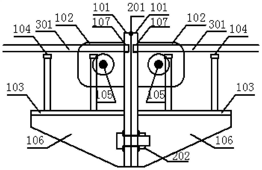
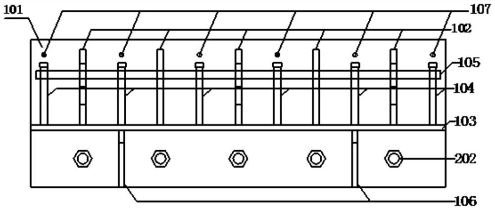
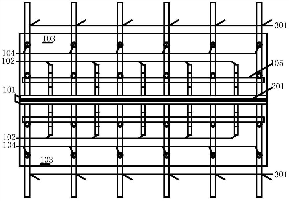
[0070] Such as figure 1 , figure 2 and image 3 As shown, the embodiment of the present invention provides a passive anti-cracking enhanced prefabricated bridge deck connection structure, including end connectors arranged at the ends of the concrete slab, and the end connectors include vertical plates 101 located on the side of the concrete bridge deck and the transverse plate 103 on the underside of the concrete bridge deck;

[0071] A plurality of perforated stiffening plates 102 are vertically arranged on the side of the vertical plate 101, steel bars 105 are pierced in the holes of the perforated stiffening plates 102, and both the perforated stiffening plates 102 and the steel bars 105 are buried in the concrete bridge deck; the top of the vertical plate 101 A plurality of reinforcement connection holes 107 are provided, and the main reinforcement bars 301 of the bridge deck are inserted into the reinforcement connection holes 107, and the main reinforcement bars 301 o...

Embodiment 2

[0082] Based on the connection structure described in the above-mentioned embodiment 1, the embodiment of the present invention also provides a design method of a passive anti-cracking enhanced prefabricated bridge deck connection structure, including the following steps:

[0083] S1. Set the size of the above-mentioned connection structure, the allowable crack width at the interface between the vertical slab and the side of the concrete bridge deck, and the spacing between the stiffened slabs with holes;

[0084] In this embodiment, the present invention determines the length, width, and thickness of the vertical slab, stiffened slab with holes, transverse slab, and stiffener according to the structural requirements, wherein the width of the vertical slab and the width of the transverse slab are the same width as the width B of the bridge deck; Determine the allowable crack width at the interface between the vertical slab and the side of the concrete bridge deck according to t...


PUM


Abstract

The invention discloses a passive anti-crack reinforced prefabricated bridge deck slab connecting structure and a design method thereof, the connecting structure comprises an end connecting piece arranged at the end of a concrete slab, and the end connecting piece comprises a vertical plate located on the side face of a concrete bridge deck slab and a transverse plate located on the bottom face of the concrete bridge deck slab; the vertical plate is provided with a plurality of stiffening plates with holes in the vertical direction, reinforcing steel bars penetrate through the holes, and the stiffening plates with the holes and the reinforcing steel bars in the holes are all embedded in the bridge deck slab. A plurality of reinforcing steel bar connecting holes are formed in the top of the vertical plate, and the bridge deck slab stress main reinforcing steel bars are inserted into the reinforcing steel bar connecting holes and reliably connected with the vertical plate; one end of the transverse plate is connected with the vertical plate, and the upper surface of the transverse plate is provided with a shear connector connected with a concrete bridge deck. The anti-cracking performance of the interface of the vertical plate and the bridge deck slab is remarkably improved, prestress does not need to be actively applied to the interface, the tedious prestress process is omitted, prestress equipment and anchorage devices are not needed, and the problems of rigidity and durability of the bolt-welding connection steel-concrete interface are solved.

Description

technical field [0001] The invention relates to the technical field of civil engineering, in particular to a passive anti-crack enhanced prefabricated bridge deck connection structure and a design method thereof. Background technique [0002] The connection forms of concrete slabs mainly include cast-in-place wet joints and dry joints. The cast-in-place wet joint is poured with concrete in the reserved post-cast zone, and the adjacent concrete slabs are connected through the cast-in-place concrete and the reserved protruding steel bars. [0003] There are two forms of dry joints, one is to apply epoxy glue on the end of the adjacent concrete slab, pass the steel strand through the reserved hole, and connect the adjacent concrete slab through epoxy glue and steel strand; The second is to pre-embed the slab end connector at the end of the concrete slab, adopt welding connection at the top of the slab end connector, and use bolt connection at the bottom of the slab end connect...

Claims


Application Information

Patent Timeline
Patent Type & Authority Applications(China)
IPC IPC(8): E01D19/12G06F30/23E01D101/26
CPCE01D19/125G06F30/23E01D2101/26Y02A30/30
Inventor 崔冰武焕陵赵灿晖刘征宇
Owner 崔冰
Why Eureka
Try Eureka