Eureka AIR delivers breakthrough ideas for toughest innovation challenges, trusted by R&D personnel around the world.

Continuous rigid frame bridge cast-in-place bracket pre-pressing device and method

A rigid-frame bridge and bracket technology is applied in the field of cast-in-place bracket preloading devices for continuous rigid-frame bridges, which can solve the problems of unreusable preloading devices, low preloading efficiency, concrete falling off, and the like, and achieve low construction investment costs. , High utilization rate, the effect of eliminating inelastic deformation

Active Publication Date: 2021-07-23
CHINA GEZHOUBA (GRP) FIRST ENG CO LTD
View PDF10 Cites 0 Cited by
  • Summary
  • Abstract
  • Description
  • Claims
  • Application Information

AI Technical Summary

Problems solved by technology

[0005]The main purpose of the present invention is to provide a continuous rigid frame bridge cast-in-place bracket preloading device and method, to solve the problem of large bridge bracket preloading for surcharge preloading When the space is not enough, the construction cost is too high, the pier cracks or the concrete falls off due to improper operation, the preloading efficiency is low, and the preloading device cannot be reused.

Method used


Image

  • Continuous rigid frame bridge cast-in-place bracket pre-pressing device and method
  • Continuous rigid frame bridge cast-in-place bracket pre-pressing device and method
  • Continuous rigid frame bridge cast-in-place bracket pre-pressing device and method

Examples


Embodiment 1

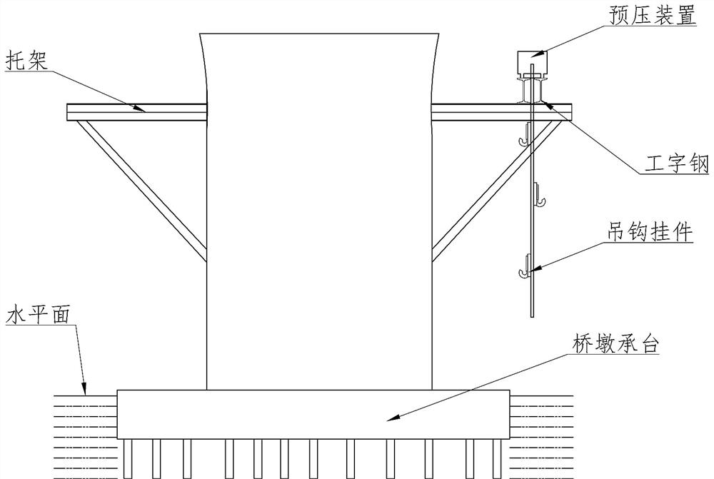
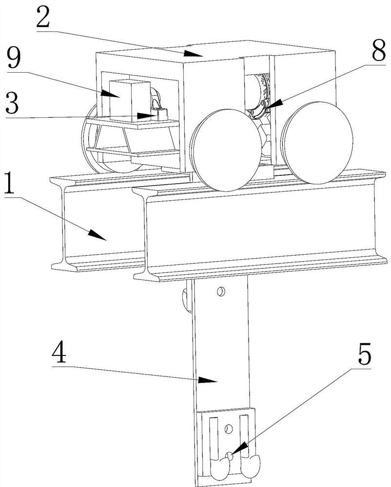
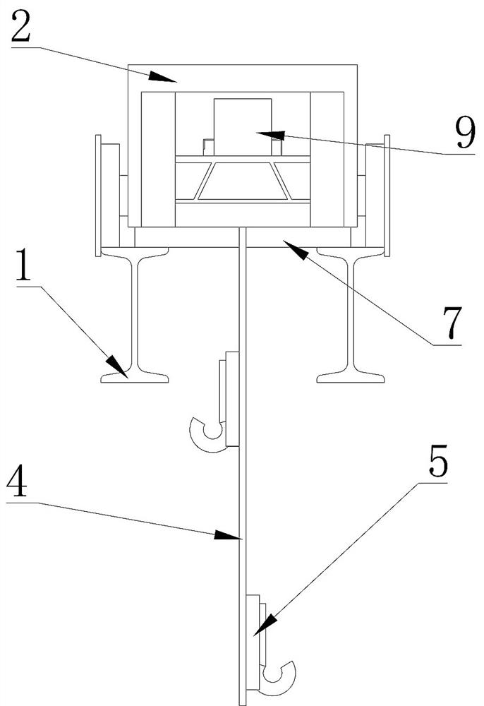
[0038] Such as Figure 1~9shows a continuous rigid frame bridge cast-in-place bracket preloading device and method, including a plurality of I-beams 1 installed on the bracket, and is characterized in that: a plurality of I-beams 1 are provided with slidable moving devices 2. The moving device 2 is provided with a rotatable rotating shaft 601. The rotating shaft 601 is provided with a through groove 602. One side of the rotating shaft 601 is provided with a motor 9. The output shaft of the motor 9 is fixedly connected with one end of the rotating shaft 601. The rotating shaft 601 is provided with a coiled steel plate sling 4, and one end of the steel plate sling 4 is fixed against the through groove 602. There are multiple detachable sling pendants 5 on both sides of the steel plate sling 4, and a shear bar is also provided on the steel plate sling 4. The hole 402, the shear rod 7 runs through the shear rod hole 402 and leans against the shear rod hole 402, and the two ends of...

Embodiment 2

[0050] Further illustrate in conjunction with embodiment 1, as Figure 1~9 As shown, the method is: in the factory, the shear bar 7 and the suspender 5 are processed and formed according to the appropriate situation, and the steel plate suspender 4 is opened according to the size of the shear bar 7 and the suspender 5; the steel plate is placed on the ground. One end of sling 4 is fixed in the through groove 602 by fixing column 604, and motor 9 drives rotating shaft 601 to rotate, and drives steel plate sling 4 to wind up on rotating shaft 601, and reserved sling pendant 5 is not installed on steel plate sling 4; The preloading device of the cast-in-place bracket of the bridge is hoisted on the bracket as a whole, the position of the I-beam 1 installed on the bracket is adjusted, and the distance between the I-beam 1 is adjusted so that the I-beam 1 just passes through the sling pendant 5 and the Install and connect the steel plate sling 4, fix the I-beam 1 on the top surface...


PUM


Abstract

The invention provides a continuous rigid frame bridge cast-in-place bracket pre-pressing device and method. The continuous rigid frame bridge cast-in-place bracket pre-pressing device comprises a plurality of pieces of I-shaped steel which are provided with slidable moving devices, a rotatable rotating shaft is arranged in the moving devices, a through groove is formed in the rotating shaft, a motor is arranged on one side of the rotating shaft, and an output shaft of the motor is fixedly connected with one end of the rotating shaft; a rolled steel plate hanging belt is arranged on the rotating shaft, one end of the steel plate hanging belt abuts against the through groove to be fixed, a plurality of detachable hanging belt hanging pieces are arranged on the two sides of the steel plate hanging belt, shear bar holes are further formed in the steel plate hanging belt, shear bars penetrate through the shear bar holes to abut against the shear bar holes, and the two ends of each shear bar abut against the top of the I-shaped steel. The motor drives the rotating shaft to rotate, drives the steel plate hanging belt wound on the rotating shaft to be unwound and drives the hanging belt hanging piece to move. The pre-pressing device is high in utilization rate, low in input cost, simple to operate, time-saving and labor-saving, and does not cause fatigue to personnel. The method does not perform back pressure on the pressure beam, does not pre-embed deformed steel bars or fix steel strands on the pier top, and is suitable for popularization and application.

Description

technical field [0001] The invention relates to the field of preloading of bracket bridges, in particular to a preloading device and method for cast-in-place brackets of continuous rigid frame bridges. Background technique [0002] During the construction of continuous rigid-frame bridges with high piers, because the piers are often 30 to 40 meters long and are generally close to the river bank, the traditional full-house support method is not feasible for construction, and it is often necessary to use brackets for 0# block cast-in-place In construction, some super-large bridges even require that the 1# beam section must be cast-in-place with brackets in the design. In order to ensure construction safety, eliminate the inelastic deformation of the bracket, and determine the law of elastic deformation, it is often necessary to preload the bracket structure. In the prior art, in addition to using prefabricated blocks or sand bags for direct surcharge preloading when the prelo...

Claims


Application Information

Patent Timeline
Patent Type & Authority Applications(China)
IPC IPC(8): E01D21/00
CPCE01D21/00
Inventor 刘权厚雷闪周利剑高国航杨志洲郭金东陆浩韩荣鑫李召诚刘春雷张鹏杨云风
Owner CHINA GEZHOUBA (GRP) FIRST ENG CO LTD
Why Eureka
Eureka Blog
Learn More