
Porous-based ultrasonic-speed adsorption type compressor blade

A supersonic, adsorption technology, applied in the field of compressors, which can solve the problems of flow separation on the suction surface of the blade

Active Publication Date: 2021-07-23
NORTHWESTERN POLYTECHNICAL UNIV
View PDF9 Cites 2 Cited by
  • Summary
  • Abstract
  • Description
  • Claims
  • Application Information

AI Technical Summary

Problems solved by technology

[0006] Conventional trans / supersonic adsorption compressor blades / cascades all use boundary layer suction to pump out low-energy fluid after the shock wave to improve the aerodynamic performance of the compressor, but there is still flow separation on the suction surface of the blade after suction

Method used


Image

  • Porous-based ultrasonic-speed adsorption type compressor blade
  • Porous-based ultrasonic-speed adsorption type compressor blade
  • Porous-based ultrasonic-speed adsorption type compressor blade

Examples


Embodiment Construction

[0037] This embodiment is a porous supersonic adsorption compressor blade, the original blade of the supersonic adsorption compressor blade adopts the prior art, the inlet geometric angle is 14°, the outlet geometric angle is -14°; the blade height is 100mm , the blade chord length is 65mm.

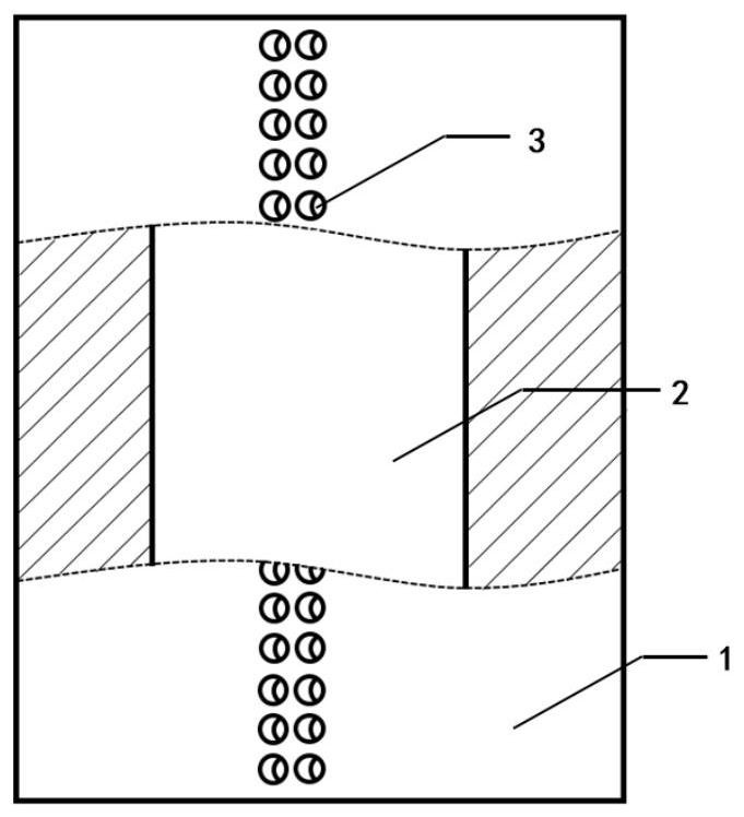
[0038] There is a suction chamber 2 between the suction surface and the pressure surface of the blade of the supersonic adsorption compressor, and the suction chamber penetrates the blade of the supersonic adsorption compressor along the span direction of the blade. The profile of the upper surface of the suction cavity is the same as the profile of the original blade suction surface of the supersonic adsorption compressor blade; the profile of the lower surface of the suction cavity is the same as the original blade pressure of the supersonic adsorption compressor blade The profiles of the surfaces are the same; the leading edge and the trailing edge of the suction chamber 2 are arc-shap...


PUM

PropertyMeasurementUnit
Radiusaaaaaaaaaa
Wall thicknessaaaaaaaaaa
Radiusaaaaaaaaaa

Abstract

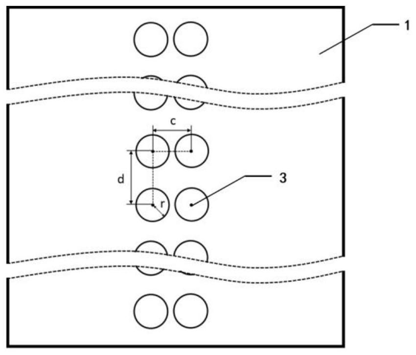
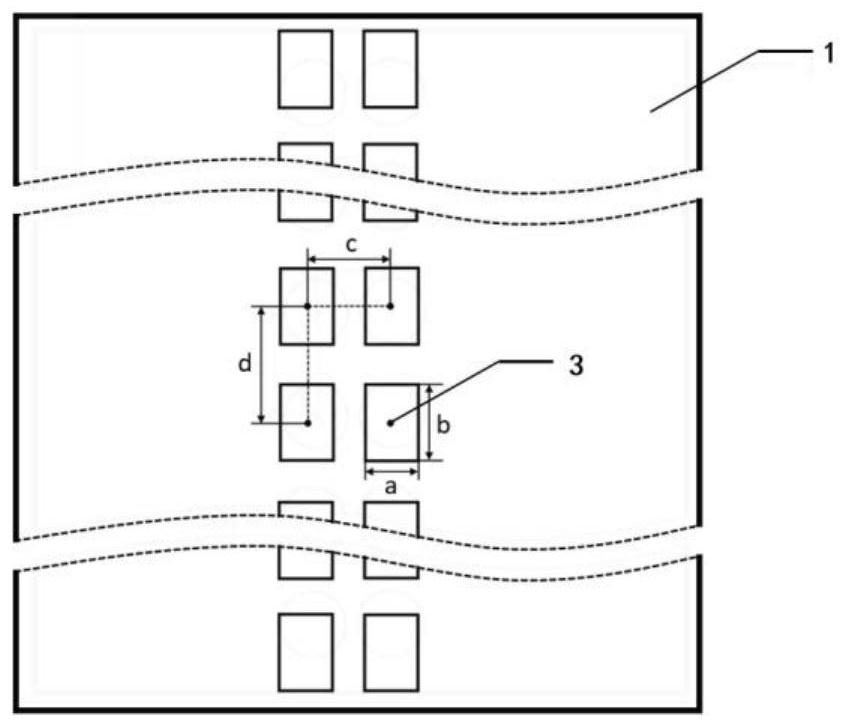
The invention discloses a porous-based ultrasonic-speed adsorption type compressor blade. A suction chamber which is through in a blade extending direction is arranged between a suction surface and a pressure surface of the ultrasonic-speed adsorption type compressor blade. A plurality of suction holes which communicate with the suction chamber are distributed in the suction surface of the ultrasonic-speed adsorption type compressor blade. Each suction hole is a circular hole or a rectangular hole with the same cross section area. Blade spacing on a gate plate, of the ultrasonic-speed adsorption type compressor blade is 30.55 mm, and a mounting angle is 47 degrees; during numerical simulation under a designed working condition, an inlet gas flow angle is 61 degrees, and an inlet Mach number is 1.5. The porous-based ultrasonic-speed adsorption type compressor blade avoids reflection, on the suction force, of shock waves, reduces loss of passing shock waves; and meanwhile, shock wave impact points are in the suction holes, so that mutual interference between the shock waves and the attaching layer of the suction force are effectively weakened, an attaching layer separation phenomenon after shock waves is effectively inhibited, too great Mach after before shock waves due to continuous acceleration, on the suction force, of the gas flow is avoided, and Mach number before waves and shock wave loss are reduced.

Description

technical field [0001] The invention relates to the field of compressors, in particular to a supersonic adsorption compressor blade based on porous control shock wave / wall interference. Background technique [0002] The development of modern aero-vehicle technology requires to further increase the thrust-to-weight ratio of aero-engines, that is, fewer stages and higher stage loads. Inside the compressor, higher stage loads are usually accompanied by unavoidable flow separation, and the flow loss and blockage caused by strong flow separation limit the increase of compressor stage loads, especially in trans- and supersonic compressors. Waves complicate the flow inside the compressor. Therefore, it is necessary to control the flow separation inside the compressor. [0003] Since Kerrebrock of MIT first proposed the adsorption compressor in 1997, the adsorption compressor has gradually become an important research direction to improve the performance of the compressor. Schule...

Claims


Application Information

Patent Timeline
IPC IPC(8): F04D29/38F04D29/66F04D21/00
CPCF04D29/324F04D29/667F04D29/666F04D21/00F05D2220/3216
Inventor 曹志远宋澄高玺张飞张翔
Owner NORTHWESTERN POLYTECHNICAL UNIV
Learn More