Compressor blade and compressor flow separation control method

A technology of flow separation and control method, which is applied in the direction of pump control, machine/engine, mechanical equipment, etc., and can solve the problems of blade strength decrease, separation loss increase, and aggravated flow separation

Active Publication Date: 2020-11-03
AECC COMML AIRCRAFT ENGINE CO LTD
View PDF8 Cites 0 Cited by
  • Summary
  • Abstract
  • Description
  • Claims
  • Application Information

AI Technical Summary

Problems solved by technology

For the airfoil pressure surface of the compressor, the adverse pressure gradient is small and the boundary layer is relatively thin, but on the suction surface of the airfoil, that is, the back surface of the blade, the adverse pressure gradient is relatively large, and the boundary layer is thick and develops rapidly, reaching To a certain extent, it will cause the separation loss of the boundary layer, and even in the case of high Mach number, it will cause shock wave-boundary layer interference, aggravate the flow separation, and lead to a sharp increase in the separation loss
This will greatly reduce the performance of the compressor, and even cause very serious consequences
[0003] When the compressor works at a non-design point, when the flow rate of the compressor decreases, the angle of attack of the airflow entering the cascade channel will increase. In the case of a large angle of attack, the airflow will easily separate at the back of the blade, resulting in a large loss increase, the performance of the compressor is significantly reduced
[0004] At present, the flow separation is mainly controlled and the loss is reduced by suctioning the boundary layer of the compressor blades. For example, the Chinese patent document CN103410779A, which was published on November 27, 2013, discloses a high-load axial flow compressor. Cascade flow separation control method, by setting suction slots at specific positions for different shapes of blades, in order to solve the problem of separation of the boundary layer caused by the increase in load and the excessive number of suction slots in high-load compressors. Difficulty in the layout of the suction pipe and the decrease in the strength of the blades
However, this is mainly aimed at forward-curved and reverse-curved blades under high-load design, which is highly targeted, so the application in other blade shapes is also limited to a certain extent.

Method used


Image

  • Compressor blade and compressor flow separation control method
  • Compressor blade and compressor flow separation control method
  • Compressor blade and compressor flow separation control method

Examples


Embodiment Construction

[0018] The present invention will be further described below in conjunction with specific embodiment and accompanying drawing, set forth more details in the following description so as to fully understand the present invention, but the present invention can be implemented in many other modes different from this description obviously, Those skilled in the art can make similar promotions and deductions based on actual application situations without violating the connotation of the present invention, so the content of this specific embodiment should not limit the protection scope of the present invention.

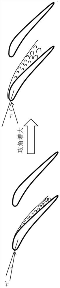
[0019] Such as figure 1 As shown, under non-design conditions, such as when the compressor flow rate decreases, the compressor blade profile is at a positive angle of attack, and the angle of attack is +i'. When the reverse pressure gradient is small and the positive angle of attack is small The surface layer will separate at the back of the blade, resulting in an increase in ...


PUM


Abstract

The invention provides a gas compressor blade and a flowing separation control method for a gas compressor. The gas compressor has a good working state under the working conditions of the large flow and the small flow. The gas compressor blade comprises a blade body and an edge-covering part, the blade body is made of a non-metallic material, and the tail edge part of the blade body is subjected to edge covering by the edge-covering part, wherein the edge-covering part is made of a memory alloy material; and the gas compressor blade further comprises an electric heating device and a piezoelectric conversion switch which are arranged in the blade body, and the piezoelectric conversion switch starts the electric heating device according to the pressure change of the tail edge of the blade back of the blade body, so that the edge-covering part is heated by the electric heating device, a low-temperature phase of the edge-covering part enables the tail edge of the blade body to be kept in afirst tail edge shape, a high-temperature phase of the edge-covering part enables the tail edge of the blade body to be kept in a second tail edge shape, and the first tail edge shape and the secondtail edge shape are suitable for different attack angle working conditions of the blade correspondingly.

Description

technical field [0001] The invention relates to a compressor blade and a flow separation control method of the compressor. Background technique [0002] In the design of modern aeroengines, the compressor is required to have the characteristics of high pressure ratio and high efficiency, and the compressor is also required to have a sufficient stable working range. The main function of the compressor is to compress the air to increase its pressure and provide high temperature and high pressure gas for the combustion chamber. Due to the viscosity of the gas, there is always a boundary layer when it flows over the surface of the compressor blade. As the air flows through each stage of the compressor, the pressure increases, and the gas is in a reverse pressure gradient environment. For the airfoil pressure surface of the compressor, the adverse pressure gradient is small and the boundary layer is relatively thin, but on the suction surface of the airfoil, that is, the back s...

Claims


Application Information

Patent Timeline
Patent Type & Authority Patents(China)
IPC IPC(8): F04D29/38F04D27/00
CPCF04D27/002F04D29/386F04D29/388
Inventor 戴磊羌晓青
Owner AECC COMML AIRCRAFT ENGINE CO LTD
Why Eureka
Try Eureka