
A Direct Sequence Time Correlation Photon Counting Error Compensation Method

A photon counting and time-related technology, used in radio wave measurement systems, instruments, etc., can solve problems such as low system accuracy, large variance, and complex circuits, and achieve the effect of improving system accuracy.

Active Publication Date: 2022-07-15
NANJING VOCATIONAL UNIV OF IND TECH
View PDF0 Cites 0 Cited by
  • Summary
  • Abstract
  • Description
  • Claims
  • Application Information

AI Technical Summary

Problems solved by technology

[0003] First, the existing systems mostly use one channel to transmit direct sequences and the other channel to generate synchronous high level for detection. The problem with this technology is that the high level pulses are often not completely synchronized with the time when the code starts to be sent, especially in When sending a high stream rate, this asynchrony will lead to the offset of the code pattern reconstruction, which will lead to problems such as the broadening of the time-related function waveform and the decrease of depth accuracy; and some use an external phase-locked loop to solve the synchronization problem. system with sexual problems, the complexity of the hardware system increases
[0004] Second, the accuracy of the system is also one of the key performance parameters. Due to the existence of environmental factors, such as noise and uncertain factors such as target materials, there must be measurement errors in the direct sequence time-correlated photon counting depth imaging method. It has been reported that the The main reason for the error is that there is a "time walking error" or "time jitter" in the photon detector, that is, the more the number of photons detected per unit time, the greater the lead time of the resulting time arrival point, and the higher the system accuracy. Low, in this type of system, due to the "time-walking" effect of the Geiger mode avalanche diode, the time arrival point of multiple photons will shift, which will inevitably bring about the overall displacement of the time correlation function. It is necessary to give the Offset compensation method; and the offset compensation threshold comparison circuit for the Geiger mode avalanche diode itself is too complicated and has poor applicability; simple function fitting method, (such as: Weiji He, Bo yu Sima, Yun fei Chen, Hui dong Dai, Qian Chen, Guo hua Gu. Acorrection method for range walk error in photon counting 3D imaging LIDAR[J]. Optics Communications, 2013, 308(1):211-217. Shanshan shen, Chen Qian, HeWeiji, et al al.Boundary evaluation and error correction on Pseudo-random spreadspectrum photon counting system[J].Chinese Optics Letters, 2017, 15(9):090101-1-090101-6.)
Although the depth accuracy can be improved, the depth offset variance of low SNR and high SNR has obvious heterogeneity, and the variance of each component of the least squares estimator of the parameter is large, resulting in the difference between the estimated value and the real value. The fluctuation increases, that is, the heteroscedasticity in the model makes it no longer have the minimum variance, resulting in a decrease in the estimation accuracy, and the correction of the photon count rate is not considered, so the method is not effective in actual imaging

Method used


Image

  • A Direct Sequence Time Correlation Photon Counting Error Compensation Method
  • A Direct Sequence Time Correlation Photon Counting Error Compensation Method
  • A Direct Sequence Time Correlation Photon Counting Error Compensation Method

Examples


Embodiment Construction

[0049] In order to make the above objects, features and advantages of the present invention more clearly understood, the specific embodiments of the present invention will be described in detail below with reference to the accompanying drawings.

[0050] Next, the present invention is described in detail with reference to the schematic diagrams. When describing the embodiments of the present invention in detail, for the convenience of explanation, the cross-sectional views showing the device structure will not be partially enlarged according to the general scale, and the schematic diagrams are only examples, which should not be limited here. The scope of protection of the present invention. In addition, the three-dimensional spatial dimensions of length, width and depth should be included in the actual production.

[0051] In order to make the objectives, technical solutions and advantages of the present invention clearer, the embodiments of the present invention will be furth...


PUM


Abstract

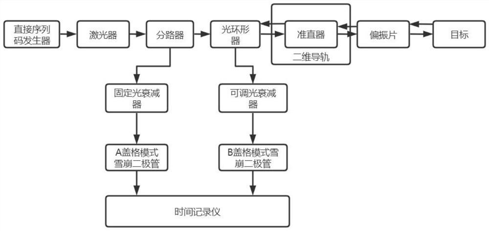
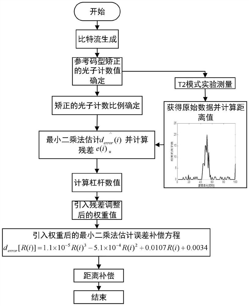
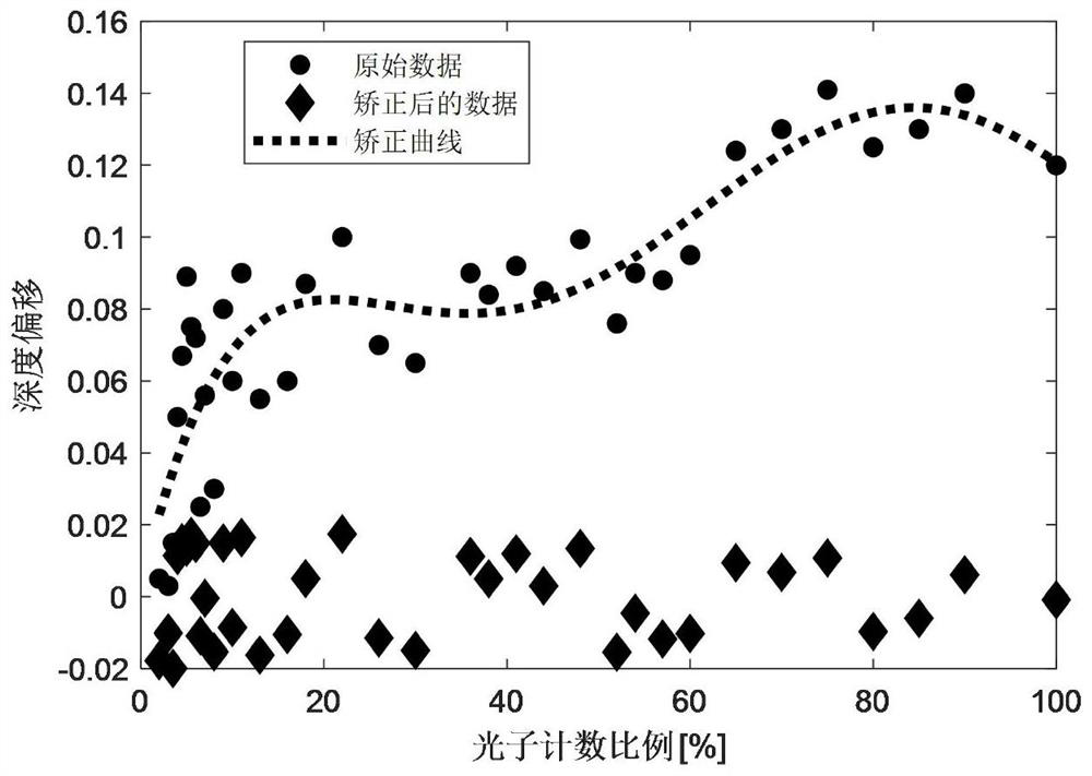
The invention discloses a direct-sequence time-correlated photon counting error compensation method. The specific steps are as follows. Through area array scanning, the photon count value R detected by the pixel corresponding to the xth row and the y column is corrected. detect (x, y), according to the formula, calculate the corrected photon count value, adjust the fixed optical attenuator corresponding to the A Geiger mode avalanche diode, so that the corrected photon count of the A Geiger mode avalanche diode arrival time recorder value R actual (x, y) is equal to the number of direct sequence codes that are 1, as the photon count value of the reference path, denoted as R base , by adjusting the polarizer and the adjustable optical attenuator to reduce the light intensity of the reflected echoes successively, and obtain N groups of reflected echoes with different light intensities, set the B Geiger mode avalanche diode to detect the photons of the i-th group of reflected echoes number as R det (i), the direct-sequence time-correlated photon counting error compensation method can compensate depth errors with high precision in real time, correct depth images, and further improve measurement accuracy.

Description

technical field [0001] The invention relates to the technical field of laser ranging, in particular to a direct sequence time correlation photon counting error compensation method. Background technique [0002] In recent years, research on direct-sequence time-correlated photon counting-based depth imaging systems has been widely developed. [0003] First, the existing systems mostly use a method of transmitting a direct sequence and generating a synchronous high level for detection. The problem with this technology is that the high-level pulse often cannot be completely synchronized with the time when the code starts to be sent, especially in the case of When sending a high stream rate, this asynchrony will cause the offset of the code pattern reconstruction, which will lead to the broadening of the time-correlated function waveform and the decrease of depth accuracy. Some use an external phase-locked loop to solve the synchronization problem. The system with sexual proble...

Claims


Application Information

Patent Timeline
Patent Type & Authority Patents(China)
IPC IPC(8): G01S7/497
CPCG01S7/497
Inventor 沈姗姗陈钱何伟基顾国华
Owner NANJING VOCATIONAL UNIV OF IND TECH
Learn More