

TOF camera calibration method and system and calibration box
A box and calibration board technology, applied in image analysis, image enhancement, instruments, etc., can solve the problems of low depth accuracy and poor calibration efficiency, and achieve the effect of improving depth accuracy, improving calibration efficiency, and reducing depth errors
- Summary
- Abstract
- Description
- Claims
- Application Information
AI Technical Summary
Problems solved by technology
Method used
Image

Examples
Embodiment 1
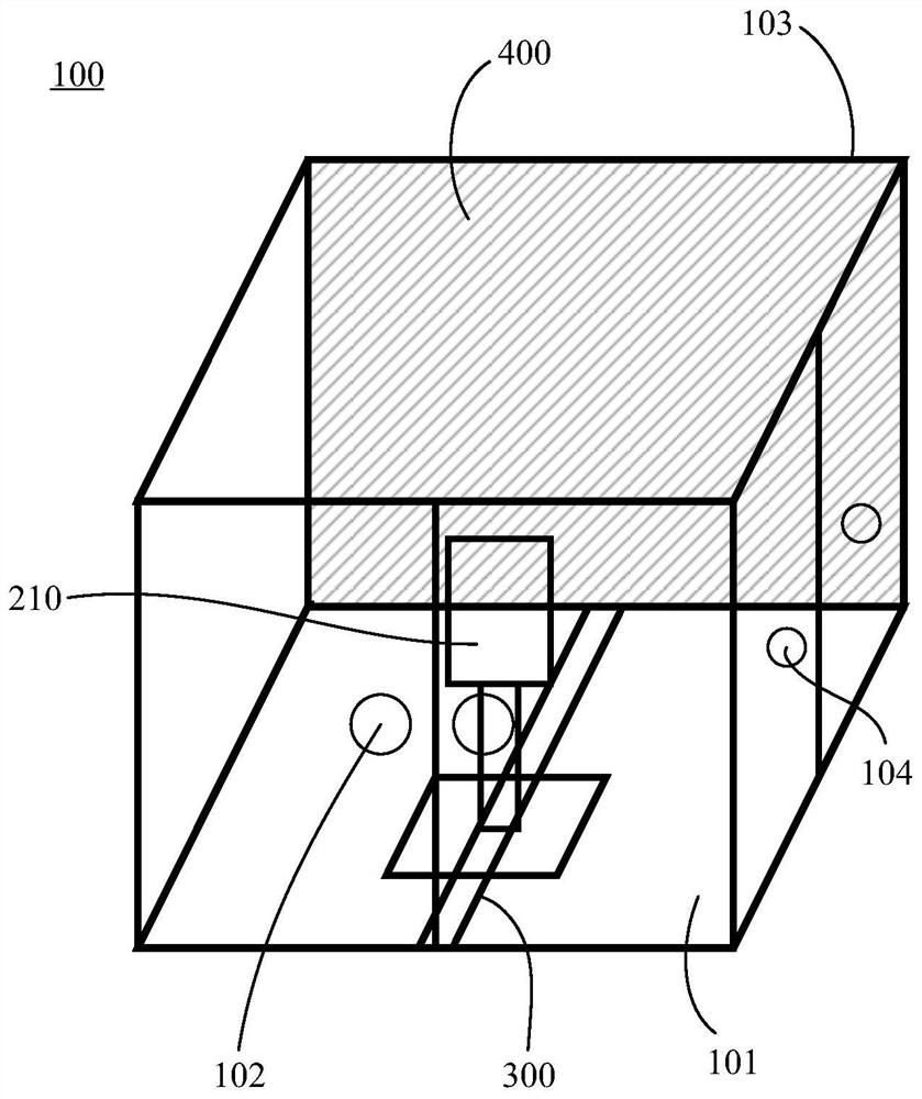
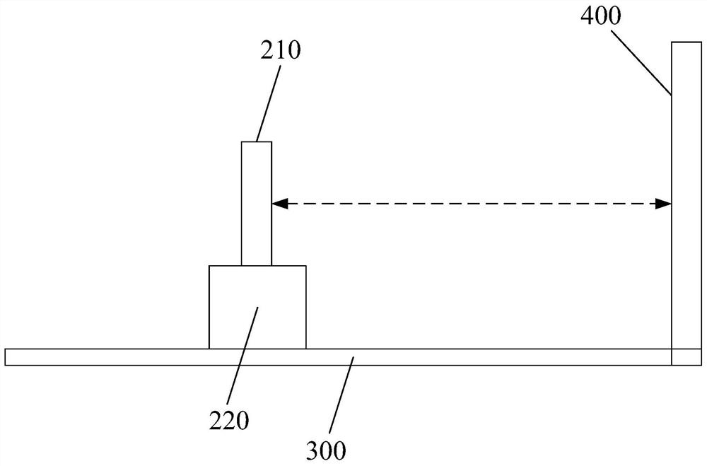
[0055] Such as figure 1 and figure 2 As shown, Embodiment 1 of the present application discloses a calibration box 100 . The calibration box 100 is a closed box. When the calibration box 100 is used for calibration operations, the closed box can ensure that external light will not enter the work site and cause additional interference. In a preferred embodiment, the calibration box 100 is in the shape of a cuboid.
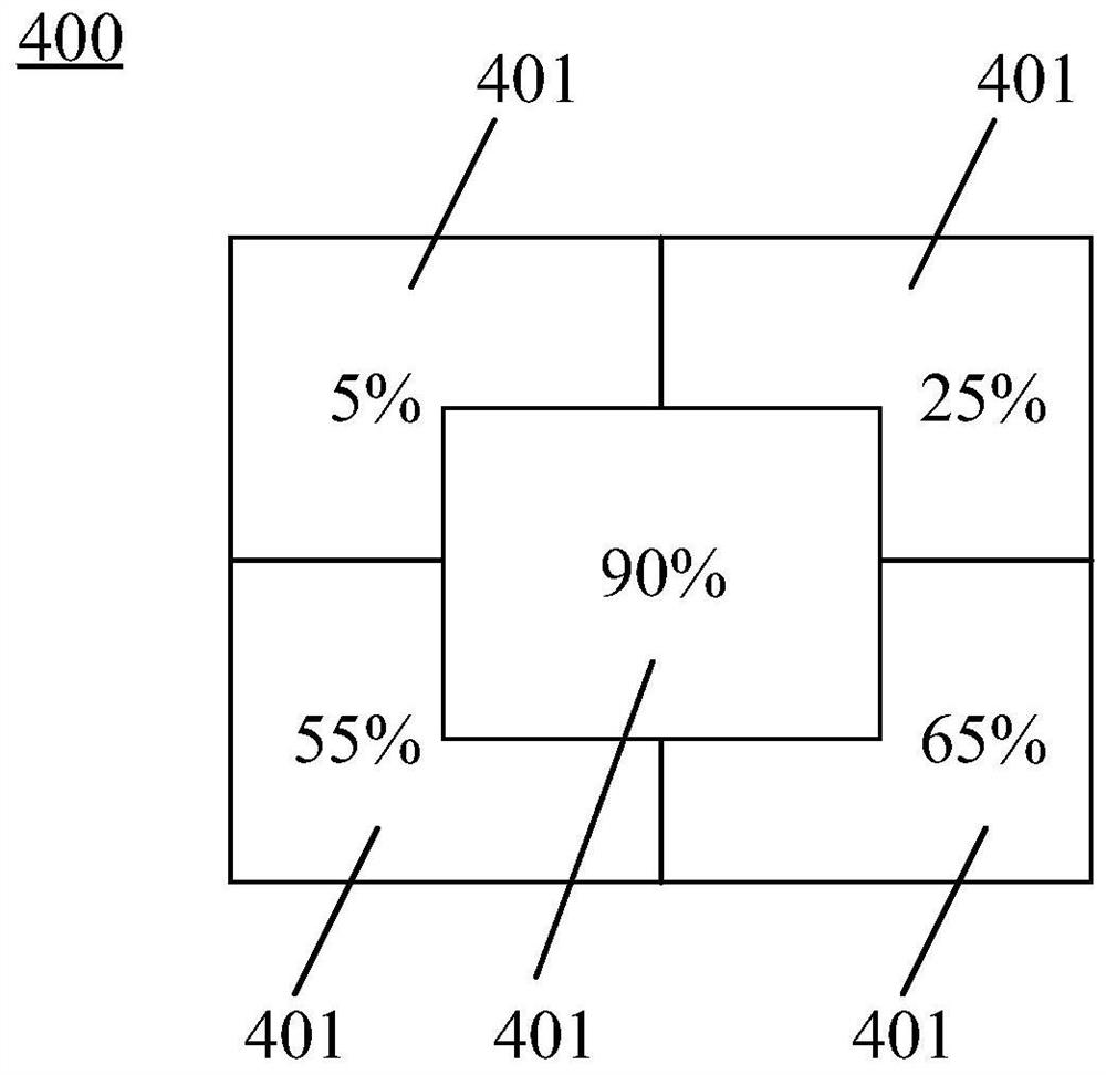
[0056] The inside of the calibration box 100 is provided with a TOF device 210 , a slide table 220 , a track 300 and a calibration plate 400 .
[0057] Specifically, there is a light-shielding layer on the outer surface of the calibration box 100 , and a light-absorbing layer on the inner surface of the calibration box 100 . The light-shielding layer can prevent the TOF device 210 from being disturbed by external light during calibration, and at the same time, the light-absorbing layer can absorb the reflected signal reflected from the calibration plate 400, the...
Embodiment 2
[0078] Such as Figure 4 As shown, Embodiment 2 of the present application discloses a TOF device calibration system. The calibration system includes a setting module 10 , a processing module 20 , a fitting module 30 and a compensation module 40 .
[0079] Specifically, the setting module 10 is used to set the exposure time t of the TOF device n . The processing module 20 is used to plot a single exposure time t respectively n The data curve under f(t n ), and according to the data curve f(t n ), were calculated at the exposure time t n Depth information of the next N phases, and form a depth data set based on the depth information. Fitting module 30 is used for each exposure time t n Perform function fitting on the depth data set to obtain the fitting function. The compensation module 40 is used to perform depth error compensation using a fitting function. Wherein, n and N are both natural numbers.
[0080] The TOF device calibration system of this embodiment uses f...
Embodiment 3
[0085] Such as Figure 6 As shown, Embodiment 3 of the present application discloses a TOF device calibration method, which is applied to calibrate the depth error of the TOF camera. The depth error mainly comes from the odd harmonic generated by the system and the intensity change of the reflected signal. The influence of is reflected in different depth errors at different distances, and the influence of intensity changes is mainly the depth error caused by quantization errors at low intensities. The method includes the following steps:
[0086] Step100: Fix the distance between the TOF device and the calibration plate, and set the exposure time t of the TOF device n . where n is a natural number.
[0087] Step200: At a single exposure time t n The luminescence signals of different phases are emitted within, and the single exposure time t is plotted separately n The data curve under f(t n ), and according to the data curve f(t n ), were calculated at the exposure time ...
PUM
 Abstract
Description
Claims
Application Information