
Electronic equipment and power consumption control method

A technology for electronic equipment and monitoring circuits, applied in the computer field, which can solve the problems of long processing time, downtime, and long server power overload time.

Pending Publication Date: 2021-07-23
中科可控信息产业有限公司
View PDF9 Cites 5 Cited by
  • Summary
  • Abstract
  • Description
  • Claims
  • Application Information

AI Technical Summary

Problems solved by technology

[0004] At present, when performing power adjustment, the power adjustment is performed through the BMC software. It may take about 30 seconds from the detection of excessive power consumption to the limit of power consumption below a certain value, which will lead to a long processing time. In turn, the server may go down because the power supply is overloaded for too long

Method used


Image

  • Electronic equipment and power consumption control method
  • Electronic equipment and power consumption control method
  • Electronic equipment and power consumption control method

Examples


Embodiment approach

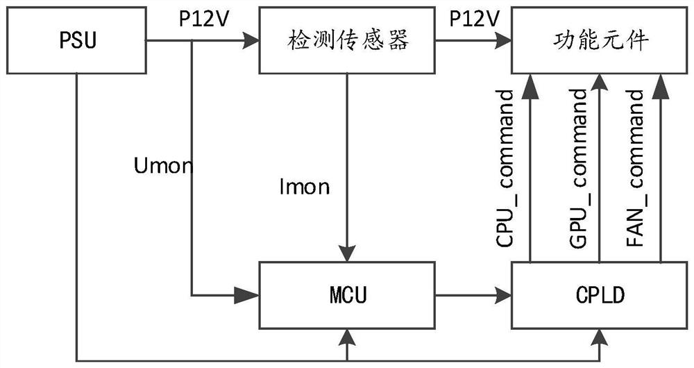
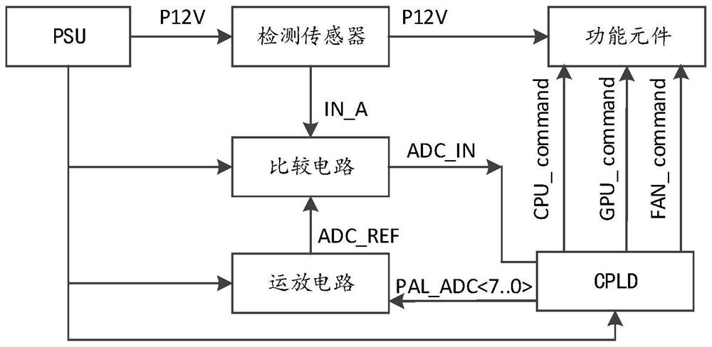
[0036] In the embodiment of this application, by using the MCU to obtain the power of the whole machine according to the output current collected by the detection sensor and the preset voltage (or the output voltage of the PSU collected in real time), when calculating the power consumption of the whole machine, it is no longer through the BMC respectively Obtain the power consumption of each part, and then add them up, but directly detect the output current proportional to the system load current to quickly obtain the power consumption of the whole machine, abandoning the traditional method of separately obtaining the power consumption of each part and then adding them up , so that the processing speed can be further improved, and the real-time adjustment of the power consumption of the system can be realized. In one embodiment, the cost can be reduced by further optimizing the solution and omitting the MCU. In this embodiment, if image 3 As shown, the monitoring circuit inc...


PUM


Abstract

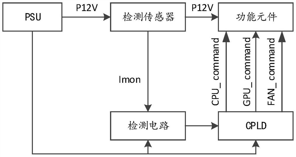
The invention relates to electronic equipment and a power consumption control method, and belongs to the technical field of computers. The electronic device comprises a detection sensor, a monitoring circuit, a PSU and a CPLD. The detection sensor is used for detecting the output current of the PSU for supplying power to the electronic equipment; the monitoring circuit is connected with the detection sensor, and the monitoring circuit is used for generating a control signal according to the output current and a preset rule; and the CPLD is connected with the monitoring circuit, and the CPLD is used for carrying out frequency reduction processing on functional elements installed on the electronic equipment according to the control signal. The control signal is generated by detecting the output current of the PSU and combining the preset rule, the CPLD is used for carrying out frequency reduction processing on the functional element installed on the electronic equipment, and power adjustment is directly carried out through CPLD hardware instead of BMC software, so that the processing time required by power consumption adjustment can be shortened.

Description

technical field [0001] The application belongs to the technical field of computers, and in particular relates to an electronic device and a power consumption control method. Background technique [0002] With the application of technologies such as big data and the Internet of Things, servers equipped with GPUs (Graphics Processing Units) emerged as the times require. As the computing capabilities of GPUs continue to increase, their power consumption also increases. Due to the existence of CPU (Central Processing Unit, central processing unit), memory, hard disk and other hardware in the server, the overall power consumption of the server will exceed the upper limit that the PSU (Power Supply Unit, power supply module) that supplies power to the server can support. [0003] In the prior art, servers usually use a Power capping (power capping) method to limit the overall power consumption of the server (including PSU input power consumption, output power consumption, CPU powe...

Claims


Application Information

Patent Timeline
Patent Type & Authority Applications(China)
IPC IPC(8): G06F1/28G06F1/3206G06F1/3296G06F11/30
CPCG06F1/28G06F1/3206G06F1/3296G06F11/3062Y02D10/00
Inventor 沙祥彪邹小兵吕厚登吴世甲晏显栋周红胜黄建新
Owner 中科可控信息产业有限公司
Learn More