
Automatic rubber cap pressing machine

A glue-pressing and automatic technology, applied in the direction of vibrating conveyors, conveyors, conveyor objects, etc., can solve problems such as difficulty in meeting large-scale production and processing, damage to lead rods, poor flexibility, etc.

Pending Publication Date: 2021-07-23
中山市雷通盛机械科技有限公司
View PDF0 Cites 0 Cited by
  • Summary
  • Abstract
  • Description
  • Claims
  • Application Information

AI Technical Summary

Problems solved by technology

[0002] During the production process of the electric heating tube, it is often necessary to press the rubber cap on the electric heating tube. At present, the pressing of the rubber cap is mostly done manually by workers through simple tooling. However, this method requires a lot of labor. High labor costs, low automation and work efficiency, and low market competitiveness make it difficult to meet large-scale production and processing
[0003] In order to improve processing efficiency and automation, cap pressing machines for pressing rubber caps on electric heating tubes have begun to appear on the market. However, due to the long length and low strength of the lead rods on the electric heating tubes, if the The hole on the tube and the lead-out rod cannot be aligned effectively, because when the rubber cap is pressed on the electric heating tube, it is easy to cause damage to the lead-out rod, and it will also cause the rubber cap to not be pressed accurately on the electric heating tube, and often appear crooked , and these problems cannot be effectively solved by the common rubber cap pressing machine, and the above-mentioned cap pressing machine is often difficult to adapt to the processing of electric heating tubes of different lengths, and the flexibility is poor

Method used


Image

  • Automatic rubber cap pressing machine
  • Automatic rubber cap pressing machine
  • Automatic rubber cap pressing machine

Examples


Embodiment Construction

[0028] The present invention will be described in further detail below in conjunction with the accompanying drawings.

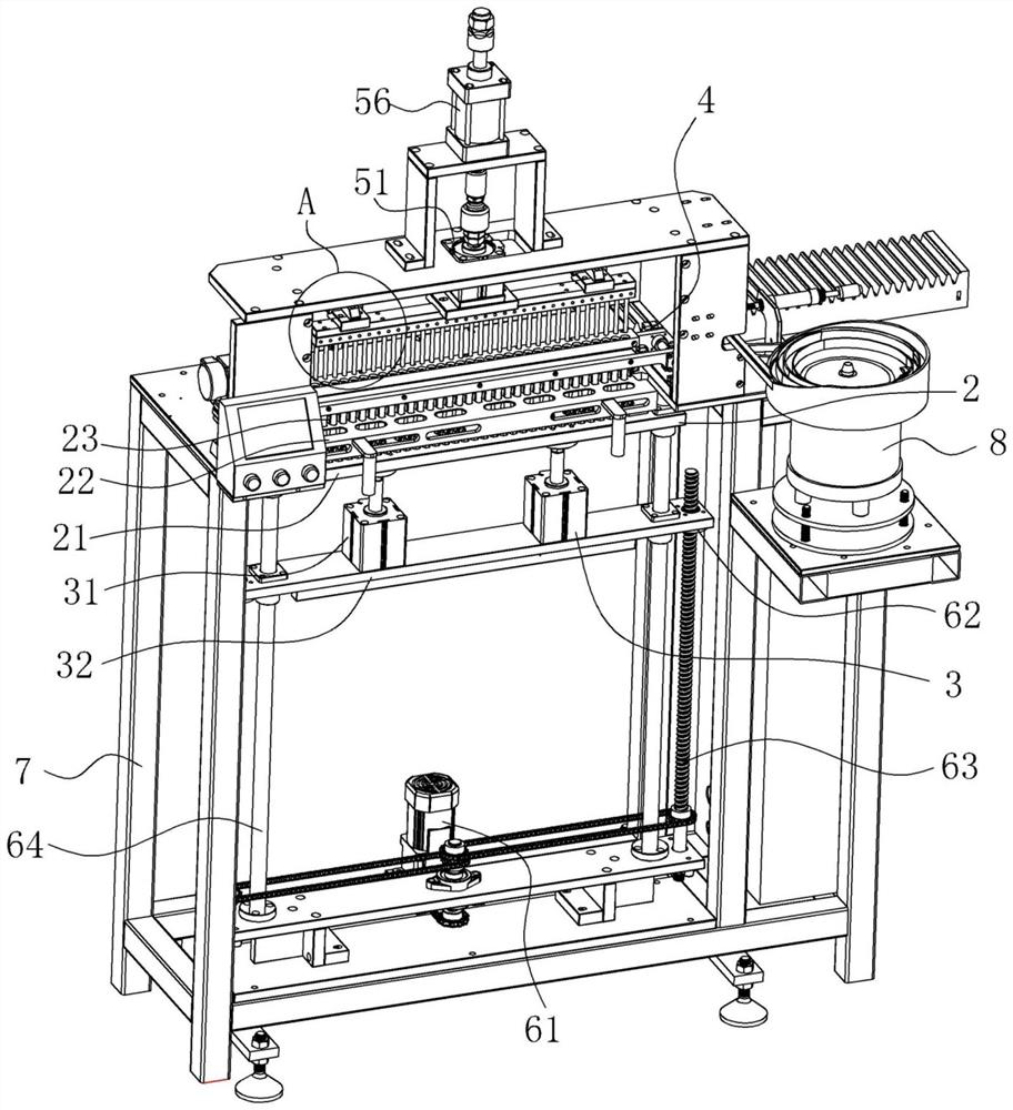
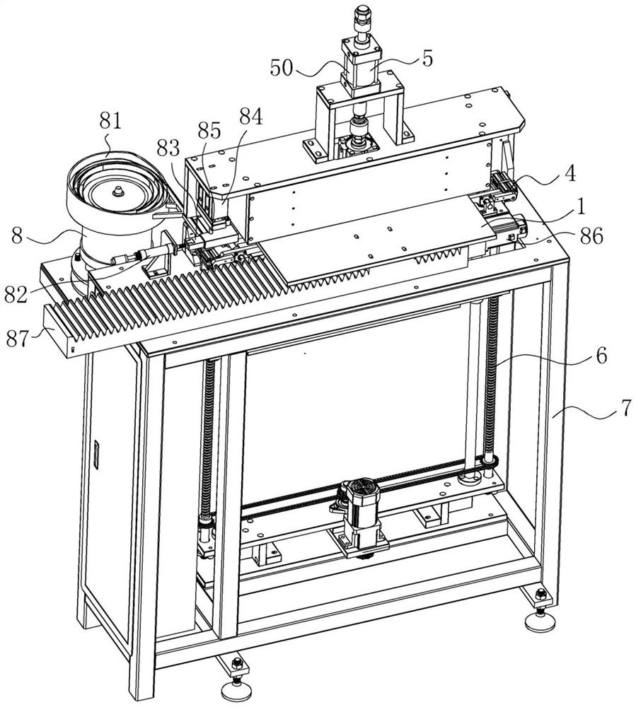
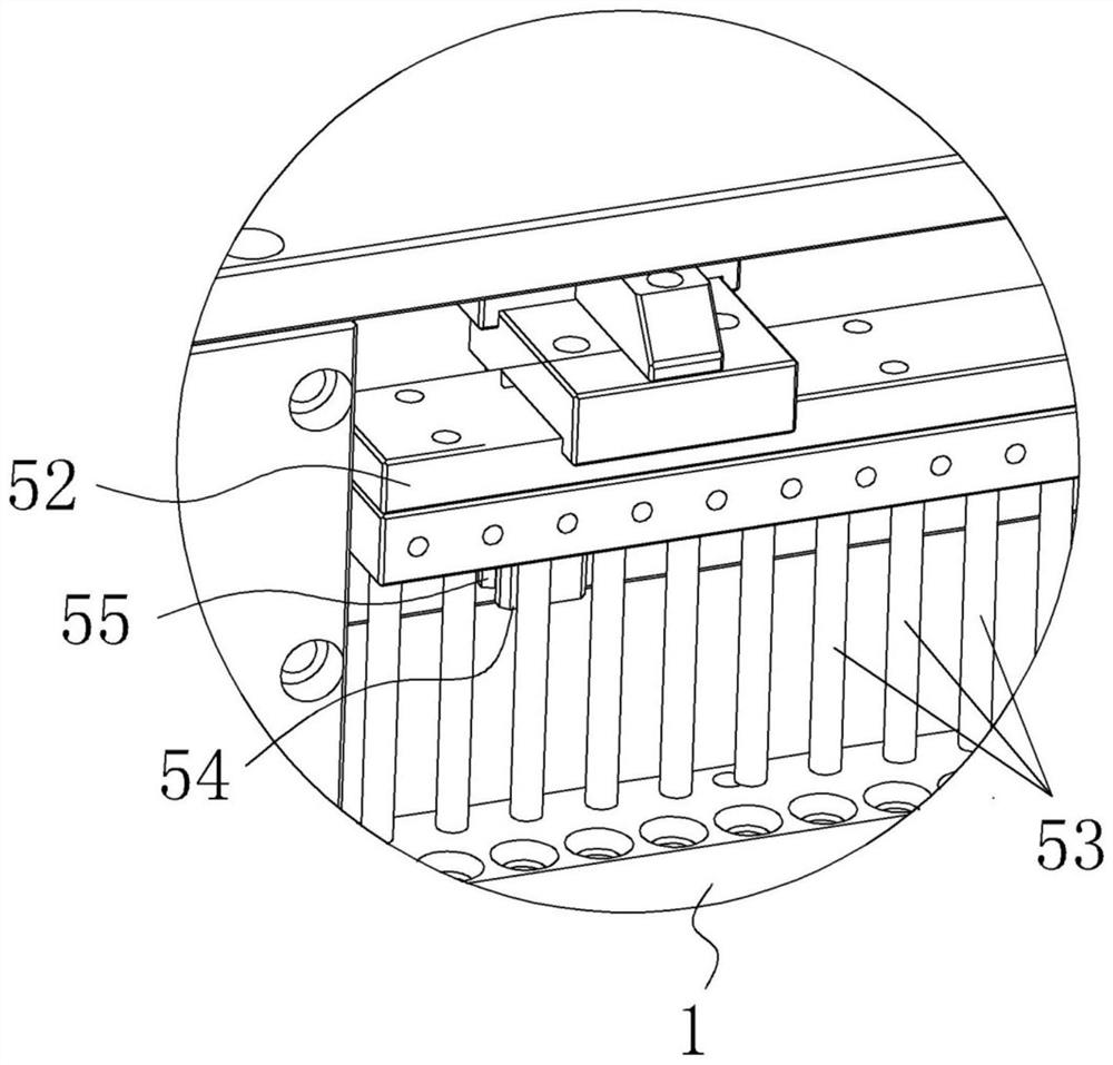
[0029] refer to Figure 1 to Figure 11 , an automatic rubber cap pressing machine of the present invention, comprising a rubber cap seat 1, an electric heating tube seat 2, a lifting mechanism 3, a clamping mechanism 4, a rubber cap pressing mechanism 5, a height adjustment mechanism 6, a frame 7 and a rubber cap Conveying mechanism 8.

[0030] The rubber cap seat 1 is provided with a plurality of rubber cap placement grooves 11, and the rubber cap accommodation grooves 11 can be used for placing the rubber caps.

[0031] The rubber cap conveying mechanism 8 includes a vibrating plate 81, a pushing cylinder 82, a push block 83, a pressing cylinder 84, a thimble 85, a stepping motor 86 and a slide rail 87. The rubber cap seat 1 is fixedly installed on the slide rail 87 by bolts, and the slide rail 87 is connected with the stepper motor 86, so that the steppe...


PUM


Abstract

The invention discloses an automatic rubber cap pressing machine. The pressing machine comprises a rubber cap seat, an electric heating tube seat, a lifting mechanism, a clamping mechanism, a rubber cap pressing mechanism, a height adjusting mechanism and a rack, wherein the rubber cap seat is used for placing a rubber cap, the lifting mechanism is connected with the electric heating tube seat, the electric heating tube seat is used for placing an electric heating tube, the clamping mechanism is used for clamping an electric heating tube placed on the electric heating tube seat, the rubber cap pressing mechanism is used for pressing a rubber cap placed on the rubber cap seat on the electric heating tube placed on the electric heating tube seat, and the height adjusting mechanism is connected with the lifting mechanism. The automatic rubber cap pressing machine is advantaged in that the clamping mechanism is arranged, when the rubber cap is pressed on the electric heating tube, the electric heating tube can be reliably fixed, so a hole in the rubber cap is accurately aligned with a lead-out rod, pressing reliability of the rubber cap is ensured, and the height of the lifting mechanism can be adjusted by arranging the height adjusting mechanism, so the height of the electric heating tube seat is adjusted; therefore, machining of the electric heating pipes with different lengths is adapted.

Description

technical field [0001] The invention relates to the field of mechanical design, in particular to an automatic rubber cap pressing machine. Background technique [0002] During the production process of the electric heating tube, it is often necessary to press the rubber cap on the electric heating tube. At present, the pressing of the rubber cap is mostly done manually by workers through simple tooling. However, this method requires a lot of labor. The labor cost is high, and the degree of automation and work efficiency is low, and the market competitiveness is low, so it is difficult to meet the large-scale production and processing. [0003] In order to improve processing efficiency and automation, cap pressing machines for pressing rubber caps on electric heating tubes have begun to appear on the market. However, due to the long length and low strength of the lead rods on the electric heating tubes, if the The hole on the tube and the lead-out rod cannot be aligned effec...

Claims


Application Information

Patent Timeline
Patent Type & Authority Applications(China)
IPC IPC(8): H05B3/40B65G27/00B65G35/00B65G47/74B65G47/90
CPCH05B3/40B65G27/00B65G35/00B65G47/74B65G47/90
Inventor 杨雷刚
Owner 中山市雷通盛机械科技有限公司
Learn More